Hi James,
I like the RCA connector, how deep does it extend under the board?
Where do you source it?
Cheers,
Jacques
Hello
The phono socket is a miniature type from RS components part number 411-071 I have attached the PDF datafile for you. There are 2 types gold plated or nickel plated .. I used nickel because the gold version was out of stock. also this size phono socket fits this size PCB very well .. normally I use a standard size socket for large PCB designs. Plus I was building a test bed for this amp to make sure all was OK before I commit to a full size finished case
Attachments
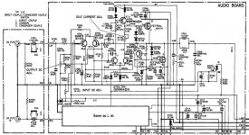
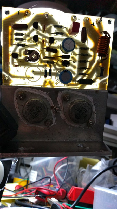
The Maplin lateral mosfet amp circuit came from the Hitachi datasheet for the lateral mosfets.
Here is my updated version.
I added better decoupling and added option for TO3 or TO247 footprints.

Here is my updated version.
I added better decoupling and added option for TO3 or TO247 footprints.
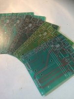
Does anyone have a source for the Maplin design HQ PSU pcb, GE29G?
The PSU is very basic, any design should work.
Attachments
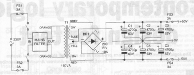
Yes, I know but I'm looking for a ready made PCB for that design with the 12v +/- regulated output as well as the higher voltages for the power amp.
I am about to buy two second hand Ga28f modules.
One module has transistors of SML type and the other is original Hitachi.
Is the SML transistors full equivalent to the original Hitachi J50/K135 types?
Will these amplifier modules work with 22V transformers?
One module has transistors of SML type and the other is original Hitachi.
Is the SML transistors full equivalent to the original Hitachi J50/K135 types?
Will these amplifier modules work with 22V transformers?
Just built up a new 75WRMS amplifier module Maplin derivative.
Based on original Maplin circuit but has a couple of improvements.
Extra front end decoupling and DC offset pot.
I added options of TO3 and TO247 footprints.
Amazing sound.

Based on original Maplin circuit but has a couple of improvements.
Extra front end decoupling and DC offset pot.
I added options of TO3 and TO247 footprints.
Amazing sound.
Hello everyone I am In need of some help I need 2 Toroidal Transformers Primary 230/240V and Secondary 35V or 36V, 300VA. If anyone has 2 leftover from one of these projects let me know. Much appreciated !

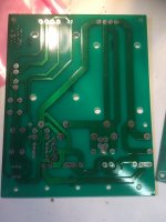
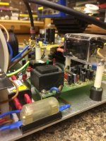
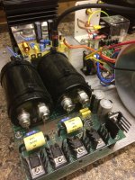
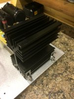
a few more pics of the PSU pcb
Attachments
Last edited:

I am about to buy two second hand Ga28f modules.
One module has transistors of SML type and the other is original Hitachi.
Is the SML transistors full equivalent to the original Hitachi J50/K135 types?
Will these amplifier modules work with 22V transformers?
Hello yes these are equivalents .. but best to use as a matched pair from the original manufacturer supplier .. I always use 35v 0v 35v secondarys but this can be increased to 40v secs with the correct rated power mosfets
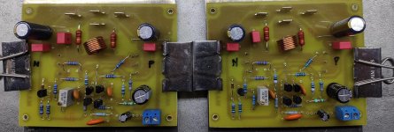
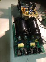
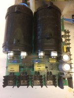
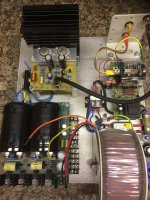
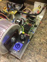
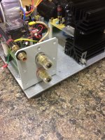
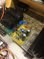
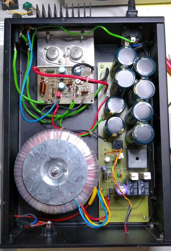
Ok a few pics of my little test bench before I commit to an expensive case, just to make sure all is ok. I have used a 300va 35v 0v 35v secondary winding toroidal transformer (5 amps on the sec) have used a k4700 protection module modified for single channel heavy duty. And a power supply that I have used for years with very good results and a old pair of nos MOSFETS .. please remember this is work in progress and not completed 100% yet will also add a earth lift switch to stop ground loops etc
Attachments
-
 IMG_0200.jpg700.7 KB · Views: 233
 -
 IMG_0201.jpg647.7 KB · Views: 221
 -
 IMG_0202.jpg558.2 KB · Views: 207
 -
 IMG_0204.jpg586.3 KB · Views: 210
 -
 IMG_0203.jpg507.3 KB · Views: 211
 -
 IMG_0205.jpg561.8 KB · Views: 211
 -
 IMG_0206.jpg786.8 KB · Views: 198
 -
 IMG_0207.jpg527.6 KB · Views: 191
 -
 IMG_0208.jpg507.9 KB · Views: 218
Hi all,
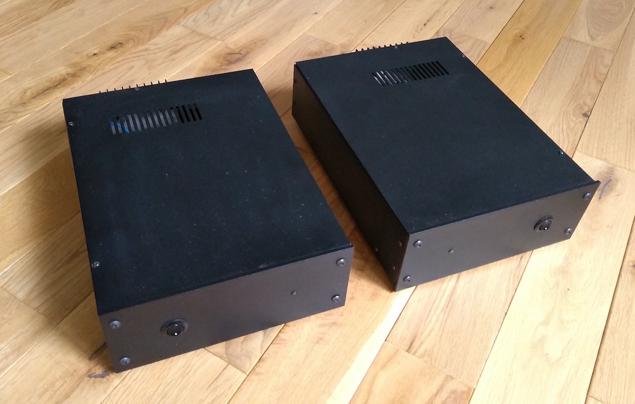
I recapped my old monoblocks while looking a little at this thread.
There's probably room for improvement, so I thought I'd show the amp..
I changed the stoppers to 220R.
Put in 470u low ESR caps.
Changed feedback cap to a Muse bipolar 47uF
Changed the input cap (used to be 1uF) to a 10uF poly (The input cap and 2.2k res are swapped to fit them onto the board).
Changed earthing to star in front of the board
Changed L1 from 10 turns to 15 (bifilar due to wire constraints).
Bias twiddle (clamp ammeter on the thick red wire) to 100mA

Some of the documentation varies... the original design has L1 10 turns and speaker ground to the main cap centers, and a 50mA bias..
Here:
Mosfet Amplifier (EMM Jun 81)
But the article in the thread states 15 turns for L1. I doubt it's critical..
The PSU is a soft start, but it's not big on fuses 😉. I designed and built it a while ago. I has an 'instant start' voltage reference, and only closes the relays (usually resistors feed the bridges) when the PSU voltage is close to what it should be. In this way it is safe to powercuts etc.
So the big caps go to the power mosfets only, the driver has it's own PSU. The idea was to help dynamics. It appears I liked caps back then, perhaps they were cheaper too 😉
With the new changes, if I plug an DAC directly in (The brilliant Apple USB-C headphone adapter) it's perfect, very nice, silent as needed...
... But if I use an old Proton pre-amp I get some mains buzz - I need to investigate that, as i don't notice any problem individually.
I doubt it's an earth loop as mains earth currently comes in via a 4.7R resistor (that I had spare - please advice the best earth decoupling method), and persists even when the amp is switched off.
Cheers.
I recapped my old monoblocks while looking a little at this thread.
There's probably room for improvement, so I thought I'd show the amp..
I changed the stoppers to 220R.
Put in 470u low ESR caps.
Changed feedback cap to a Muse bipolar 47uF
Changed the input cap (used to be 1uF) to a 10uF poly (The input cap and 2.2k res are swapped to fit them onto the board).
Changed earthing to star in front of the board
Changed L1 from 10 turns to 15 (bifilar due to wire constraints).
Bias twiddle (clamp ammeter on the thick red wire) to 100mA
Some of the documentation varies... the original design has L1 10 turns and speaker ground to the main cap centers, and a 50mA bias..
Here:
Mosfet Amplifier (EMM Jun 81)
But the article in the thread states 15 turns for L1. I doubt it's critical..
The PSU is a soft start, but it's not big on fuses 😉. I designed and built it a while ago. I has an 'instant start' voltage reference, and only closes the relays (usually resistors feed the bridges) when the PSU voltage is close to what it should be. In this way it is safe to powercuts etc.
So the big caps go to the power mosfets only, the driver has it's own PSU. The idea was to help dynamics. It appears I liked caps back then, perhaps they were cheaper too 😉
With the new changes, if I plug an DAC directly in (The brilliant Apple USB-C headphone adapter) it's perfect, very nice, silent as needed...
... But if I use an old Proton pre-amp I get some mains buzz - I need to investigate that, as i don't notice any problem individually.
I doubt it's an earth loop as mains earth currently comes in via a 4.7R resistor (that I had spare - please advice the best earth decoupling method), and persists even when the amp is switched off.
Cheers.
Last edited:
- Home
- Amplifiers
- Solid State
- Maplin MosFET Amplifier GA28F construction thread