thanks luka
now
i'm going to buy a new EOI core (may be 28-28 or stronger)and ask a local shop to wind it.
is 5 turns with 5 parallel 060 wires for primary and 20 turns with 5 parallel 060 wires sufficient?
now
i'm going to buy a new EOI core (may be 28-28 or stronger)and ask a local shop to wind it.
is 5 turns with 5 parallel 060 wires for primary and 20 turns with 5 parallel 060 wires sufficient?
SMPS pictures
Hello Dears
This is a Rod Elliott SMPS that I build.
http://i129.photobucket.com/albums/...rjuris/SMPS.jpg
http://i129.photobucket.com/albums/...juris/SMPS2.jpg
http://i129.photobucket.com/albums/...erjuris/PWM.jpg
http://i129.photobucket.com/albums/...s/powers009.jpg
Good SMPS, no "humms", no "bzzzz".
weird noise from transformer
Hi!
I'm making a battery powered powersupply, wich makes 2x50V, at about 6-700W. For testing, I'm loading the power supply with 2 amplifiers, and drive them with music.
When I turn the volume to higher levels, then strange sounds are coming from the transformer (ETD44). I recorded the sound with a webcam's microphone:
http://sziget.mine.nu/~danko/aramkor/trafo_1.mp3
http://sziget.mine.nu/~danko/aramkor/trafo_2.mp3
Unfortunatelly the computer picks up a lot of noise, even when the 12V powered supply is turned off. So please ignore that noise, which is on the records...
I don't think, that the feedback is oscillating, becouse that rasping voice is not a "discrete" frequenzy. I have looked on the powersupply's output with my scope, I haven't seen any signs of oscillation.
After that, I thought, maybe the "E" cores aren't clamped perfectly. So I changed the "clamping" to a harder one, but that weird noise was the same...
Maybe, the core is saturating? I dont think... Becouse then my mosfets would blow up 🙂 There is a current limit in this SMPS, but that's only an "overload limit", not a cycle-by-cycle type current limit.
Have anyone experienced like this?
P.S.: I can post pictures of the board, and schematic, if it's needed
hi risto
can you help me too about your first posts smps?
i described problem in below posts:
222-224-226-228-230-232-239-241
now what can i do?
can you help me too about your first posts smps?
i described problem in below posts:
222-224-226-228-230-232-239-241
now what can i do?
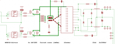
Here's the power-section, and a picture of the panel.
http://sziget.mine.nu/~danko/aramkor/car-smps/dscn0431.jpg
On the left side, there are the mosfet driver ICs.
On the right side there's a 8pin IC socket. That WAS the controlling part some time ago. That's not used, I use instead of that the TL494, on a small board.
http://sziget.mine.nu/~danko/aramkor/car-smps/dscn0431.jpg
On the left side, there are the mosfet driver ICs.
On the right side there's a 8pin IC socket. That WAS the controlling part some time ago. That's not used, I use instead of that the TL494, on a small board.
Attachments
Hi Danko
How do you solder so many wires, do you remove lacquer by hand, or there is another way?
How do you solder so many wires, do you remove lacquer by hand, or there is another way?
Hi! There are "solderable" wires, wich means, that you can remove the lacquer by heating the wire with your soldering iron. Unfortunatelly my wire isn't this type. I have to use a hungarian conservating stuff. Transating that material to english, it's called "salycic". I hope you know what i'm talking about 🙂
I pour some salycic on the table, put inside it the wire, and I heat them with my soldering iron. The salycic melts, and it gets off the lacquer from the copper. It is VERY smelly! When I soldered those wires I put about 20 wires into the salycic simultaneusly.
I pour some salycic on the table, put inside it the wire, and I heat them with my soldering iron. The salycic melts, and it gets off the lacquer from the copper. It is VERY smelly! When I soldered those wires I put about 20 wires into the salycic simultaneusly.
hey luka it finaly worked! ! !
i think the problem was putting load on one side!
i tried to load it with two 24V car bulb and worked fine!
now i'm going to test it with more load.
do you have a good x-over schematic?
best regards and thanks
delta-delta
i think the problem was putting load on one side!
i tried to load it with two 24V car bulb and worked fine!
now i'm going to test it with more load.
do you have a good x-over schematic?
best regards and thanks
delta-delta
what do you think about this?
http://sound.westhost.com/project09.htm
are there any better choice instead of x-over?
http://sound.westhost.com/project09.htm
are there any better choice instead of x-over?
That is the basic low/high 12dB/octave R/L filter.It works great as there are basic component used
hey quan thanks for your help.
which design you used in your car? 3-way or 2-way?
do you have designed pcb yet?
if yes , can you upload it?
which design you used in your car? 3-way or 2-way?
do you have designed pcb yet?
if yes , can you upload it?

transformer Kit
Yes I would be interested in one kit like that ;D
zagisrule! said:Glad to hear it 2pist 🙂
I was thinking today about offering a kit including all parts (PCB, MOSFET's, transformer, IC, misc components) for a SMPS. It would be easier for many here to make their GC car amps when all they have to do is assemble a kit and be guranteed a working design.
Would anyone be interested in something like that?
-Matt
Yes I would be interested in one kit like that ;D
Re: Commentable Thoughts
Thanks ;D
do you have pcb also?
Workhorse said:
ThanX for ur interest
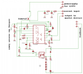
here is schematics
Thanks ;D
do you have pcb also?
tico70 said:himanshuraval,
Just a question, are you using a heatsink for the mosfets?
I am using the following circuit and it work perfectly. I am still working with two types of cores (toroid and ETD39)...for now the toroid is performing better and much easier to wind..
An externally hosted image should be here but it was not working when we last tested it.
Do you have pcb for this?
- Home
- General Interest
- Car Audio
- Making car amplifier SMPS with tl494 + DC Protection