Hi Risto
First circuit if what you want to have, 200 ohm resisitors being as load, preamp. If that is not enough you can build the one on right. There are 2 power zener that can deliver more than 1A for -/+15v. For transistor you can use any npn transistor that you can
An externally hosted image should be here but it was not working when we last tested it.
First circuit if what you want to have, 200 ohm resisitors being as load, preamp. If that is not enough you can build the one on right. There are 2 power zener that can deliver more than 1A for -/+15v. For transistor you can use any npn transistor that you can
For the preamp, he would need the negative regulated output to be 15 volts below the reference (ground) not 15 volts above the bottom rail.
He would have to use a PNP transistor for the negative regulated output. The zener and resistor on the negative regulator would have to be reversed (zener connected to ground).
He would have to use a PNP transistor for the negative regulated output. The zener and resistor on the negative regulator would have to be reversed (zener connected to ground).
Hi Perry Babin
Ah my mistake. Thanks for seeing it
Fix
Ah my mistake. Thanks for seeing it
Fix
An externally hosted image should be here but it was not working when we last tested it.
Hi
Ah today is not my day . How didn't I see that I didn't use pnp
  . Yours is what I had in my mind.
Ah today is not my day
. How didn't I see that I didn't use pnp . Yours is what I had in my mind.Hi everybody.
I was looking for a more powerful amp for my car, right now I have a Blaupunkt, 4 x 20W, and it sounds nice, but I added a 10inch woofer, so...
I already have some of the components, tomorrow I'll buy the rectifiers and the parts for the IC, I have some ST mosfets W20NB50, are they good for the smps? I also have one ETD59 core that's going in the project, is it good or should I look for a toroidal one? (the mosfets and the etd comes from a Marconi power supply, 29V, 100A)
Maybe I'll make a "carclone" or the mosfet amp from quasi's forum, the small one 😀
Greetings...
Hi LuigiDJ
I hope you won't put 20A/500v fets for car smps. Those I would use in offline halfbridge or something like that...
Don't get me wrong they are good and then some just not for car use. Irfz44 are the ones you want
I hope you won't put 20A/500v fets for car smps. Those I would use in offline halfbridge or something like that...
Don't get me wrong they are good and then some just not for car use. Irfz44 are the ones you want
Or IRF3205. If you would like to use the ETD59 at "full power", the you will need many many paralelled IRF3205 🙂
Hi
What is "full power" for you? Coz ETD49 will put out around 1kw at freq. of 50kHz, ETD59 much more than that. No really how much power can you handle during car driving for 10 min? 1kw? I don't think so.... Toroids are probably better for you if you have case of some car amp because they are pretty low and you won't get ETD59 inside.
What is "full power" for you? Coz ETD49 will put out around 1kw at freq. of 50kHz, ETD59 much more than that. No really how much power can you handle during car driving for 10 min? 1kw? I don't think so.... Toroids are probably better for you if you have case of some car amp because they are pretty low and you won't get ETD59 inside.
I have a spreadsheet, wich says, that ETD59 at 100kHz can "produce" about 2.5kW. I think, this power is for conoinous duty. In an amplifier, I think it can produce more power.
Hello Luka
Thanks for the reply, ok, I'll try the irfz44.
Hello Danko
2.5kW ?? that'll be a big amp 😀 ok, i don't intend to use it at full power, as is the only ferrite i have, i guess i'll try it.
I have 2 toroids but i don't think they are ferrites, i think they are iron cores, they were used for filtering at the input and output, is there some color code on toroids? one of them is white with some pink on one side, the other is gray with yellow.
off-topic : has anyone tried a 120vac to +/-50vdc smps? 😕
I am developing a Full bridge power supply for a friend's car subamp, it uses 4 X IRL3713[8 X IRF3205], and HIP4082 for full bridge gate driver or may be gate drive transformer which suit my needs...The transformer primary winding is just made from heat resistance wire with 22 Strands[effective thickness combined is 2.5mm] 600deg C rated and insulated is rated at 2200V.....Due to FB topology the single winding is only needed[no centre tap required] also the power rating is about 1KW, SW 54Khz
Cheers,
Kanwar
Cheers,
Kanwar
try a switchmode from newfangled u-wave oven
For the sake of public informational awareness and to help the DIY community might I reveal that modern microwave ovens have eliminated the iron step up HV xfmer and now employ a HF switchmode PSU. The one I salvaged from a scrapped oven is a really nice printed circuit package with an open ferrite core with the windings on a plastic bobbin. The heavy primary is multi strands of Litz wire IIRC and the secondary that makes the 2 kVAC is not many turns of normal magnet wire. I was thinking of the possibility of rewinding the secondary to make a tube amp plate supply. This little package will output about 3/4 or more of a kW. I have not yet had the time to experiment with my copy but I see a vast arena of potential experimental applications for such a PSU module.
For the sake of public informational awareness and to help the DIY community might I reveal that modern microwave ovens have eliminated the iron step up HV xfmer and now employ a HF switchmode PSU. The one I salvaged from a scrapped oven is a really nice printed circuit package with an open ferrite core with the windings on a plastic bobbin. The heavy primary is multi strands of Litz wire IIRC and the secondary that makes the 2 kVAC is not many turns of normal magnet wire. I was thinking of the possibility of rewinding the secondary to make a tube amp plate supply. This little package will output about 3/4 or more of a kW. I have not yet had the time to experiment with my copy but I see a vast arena of potential experimental applications for such a PSU module.
Web Site
Visit my web site www.elkomak.4t.com
Also I will these days put some other products for car amplifiers, and pleaase somebody write me an e-mail who is from America.
I have business proposal
my e-mail: elkomak@yahoo.com
Regards
Visit my web site www.elkomak.4t.com
Also I will these days put some other products for car amplifiers, and pleaase somebody write me an e-mail who is from America.
I have business proposal
my e-mail: elkomak@yahoo.com
Regards
Hi all!
Can you help me to make transformer for SMPS (http://sound.westhost.com/project89.htm)?
I found core from very old AT power supply and now I have some questions🙂
1) May I use this core?
2) Max frequency for SMPS with this core?
3) How many turns for primary ?
4) Diameter for primary wire?
5)How many power I'll get from SMPS?
Thank you and sorry for bad english.
Attachments
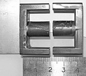
1) May I use this core?
Yes, that's a ferrite ETD39 core. It's an excellent choice. You should have a bobbin though to hold the sides together.
2) Max frequency for SMPS with this core?
I don't know the material it is made from but I would guess that 150kHz is not unreasonable.
3) How many turns for primary ?
This depends on the flux excursion and wire resistance. If you're running it off of 12v - ( I haven't read that article in a while, I'm assuming it's an automotive dc-dc ) you would want perhaps 8+8 turns if you're running at 50kHz. This is just a wild guess. "YMMV"
This depends on the power level. If you're trying to get 500 watts out, you would have an average current of 40 amps. This would mean at least 2 12 AWG wires in parallel.4) Diameter for primary wire?
5)How many power I'll get from SMPS?
Less than 500 watts.
These are just guesses. There are many important factors to consider when designing a power supply. The magnetics (transformer) are in my opinion the most difficult part to design.
Good luck. Interleave the primary with the secondary so that you have low leakage inductance. If you're kind of hacking this together anyway you want to at least do a good job where you can.
-
MK
raidfibre said:
Yes, that's a ferrite ETD39 core. It's an excellent choice. You should have a bobbin though to hold the sides together.
I don't know the material it is made from but I would guess that 150kHz is not unreasonable.
This depends on the flux excursion and wire resistance. If you're running it off of 12v - ( I haven't read that article in a while, I'm assuming it's an automotive dc-dc ) you would want perhaps 8+8 turns if you're running at 50kHz. This is just a wild guess. "YMMV"
This depends on the power level. If you're trying to get 500 watts out, you would have an average current of 40 amps. This would mean at least 2 12 AWG wires in parallel.
Less than 500 watts.
These are just guesses. There are many important factors to consider when designing a power supply. The magnetics (transformer) are in my opinion the most difficult part to design.
Good luck. Interleave the primary with the secondary so that you have low leakage inductance. If you're kind of hacking this together anyway you want to at least do a good job where you can.
-
MK
Thank you a lot!
It's just what I looking for!
raidfibre said:
Yes, that's a ferrite ETD39 core. It's an excellent choice. You should have a bobbin though to hold the sides together.
I don't know the material it is made from but I would guess that 150kHz is not unreasonable.
This depends on the flux excursion and wire resistance. If you're running it off of 12v - ( I haven't read that article in a while, I'm assuming it's an automotive dc-dc ) you would want perhaps 8+8 turns if you're running at 50kHz. This is just a wild guess. "YMMV"
This depends on the power level. If you're trying to get 500 watts out, you would have an average current of 40 amps. This would mean at least 2 12 AWG wires in parallel.
Less than 500 watts.
These are just guesses. There are many important factors to consider when designing a power supply. The magnetics (transformer) are in my opinion the most difficult part to design.
Good luck. Interleave the primary with the secondary so that you have low leakage inductance. If you're kind of hacking this together anyway you want to at least do a good job where you can.
-
MK
can you tell me how can you calculate all that ?
thanks
tamir
- Home
- General Interest
- Car Audio
- Making car amplifier SMPS with tl494 + DC Protection