There are a few good books on SMPS design including:
Power Supply Cookbook by Marty Brown (simplest)
Switchmode Power Supply Handbook by Keith Billings
Switching Power Supply Design by Abraham Pressman
Power Supply Cookbook by Marty Brown (simplest)
Switchmode Power Supply Handbook by Keith Billings
Switching Power Supply Design by Abraham Pressman
I used a radio shack book to build my first one. It may be the cookbook version, can't remember. it used a 556 timer. still using that amp in my blazer.
Before you invest too much time with these cores, you may want to check with Eva or one of the other power supply gurus in the power supply design forum. Flybacks operate differently than push-pull transformers and the core material may not be suitable for a car amplifier power supply.
supermico said:may work this core ??
those are tv flyback yokes, if they came from pc monitors, they are good for over 45khz...
raidfibre:
It's not that I don't trust you. I simply don't know how much you know about power supplies (I don't visit the other forums on a regular basis). I've seen a lot of bad information about using various cores and I know that some of the suggestions have led to frustration and failure for the people building the supplies. I suggested Eva because I've read a lot of her posts.
It's not that I don't trust you. I simply don't know how much you know about power supplies (I don't visit the other forums on a regular basis). I've seen a lot of bad information about using various cores and I know that some of the suggestions have led to frustration and failure for the people building the supplies. I suggested Eva because I've read a lot of her posts.
Ok you geniuses. I have and old pioneer amp exactly like the one linked on perry's page. Two of the switching fets were bad so I replaced them. It now powers up ok for two minutes, than It starts drawing big current and the left channel output Transistors heat up bad. I checked the output trans and they are fine. Any Ideas where to look?
toroidal core
Hi,
I'm sure this has been posted somewhere, but where can I purchase toroidal ferrite core for smps. I had looked at buying dead amps off eBay for the them but too costly. Any ideas?
shon
shon30us@gmail.com
Hi,
I'm sure this has been posted somewhere, but where can I purchase toroidal ferrite core for smps. I had looked at buying dead amps off eBay for the them but too costly. Any ideas?
shon
shon30us@gmail.com
Re: toroidal core
"F" material is good. Check out the #77 Material, too. I have ordered all of my ferrite toroids from Amidon Associates out of California. www.amidoncorp.com
One other book that taught me most of what I know about SMPSs is George Chryssis' book, "High Frequency Switching Power Supplies - Theory and Design", (c) 1989.
Steve
shon35us said:Hi,
I'm sure this has been posted somewhere, but where can I purchase toroidal ferrite core for smps. I had looked at buying dead amps off eBay for the them but too costly. Any ideas?
shon
shon30us@gmail.com
"F" material is good. Check out the #77 Material, too. I have ordered all of my ferrite toroids from Amidon Associates out of California. www.amidoncorp.com
One other book that taught me most of what I know about SMPSs is George Chryssis' book, "High Frequency Switching Power Supplies - Theory and Design", (c) 1989.
Steve
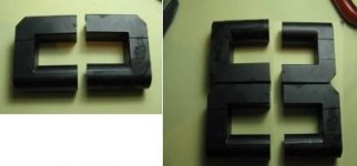
supermico said:its possible to use a ferrite cores from TVflyback?? 2 cores to form a big E cores....
been there, done that. 😀
using push pull with 6+6T pri running at about 40-45kHz, I was able to get about 400watts or so out of a pair of TV flyback cores.
the flyback transformers have plastic shims that add an airgap to the ferrite cores, REMOVE these and clean the mating surfaces well and epoxy them together. you now have a squarish 'toroid' then wind it as you would a toroid.

This supposed to be my first DIY DC-DC,as a part of some device.This scheme i didn't find on
net, i tryed to develop this device by my self, but i can't do that.
I need to have about 150W at 283V, but i don't have.
When there is no load everything works fine but when i connect light bulb (20W/220VAC)
it's consumption of current is about 4A, and when i connect light bulb (100W), consumption current is above 12A and
voltage is 210V.
Because i wound few different transformers (more than 10) i decided not to connect part of circuit after transformer.
I simply connect load directly to secondary of transformer and by Fluke187 multimeter i measure current and voltage at secondary.
When i get tired of winding transformers i decide to wind trans. with ratio of 1to1.
I also suspect that my design of current control by R0 was bad so i short-circuit it,as it can be seen on pisture 002.
I just made it to work with duty cycle of 0.5, like simple oscilator.
On picture 004, left bobbine was wound with 2x6turns in primary with 3 strand of Cu wire (fi=0.8mm),triffilary,wire by wire,i don't twist wires.
I wound primary first than i wound 186 turns of secondary(1 strand Cu wire fi=0.8mm), with insulation tapes between every two layers.
And as i described there is just 210V at 100W of consumption(>12A an primary),irfz48n at this power after a minute become very hot.
So, i made by by self Linz wire (fi=2mm) with many of very,very thin Cu wires that i have found in HV ferrite transformer from old TV.
You can see how i have wound it on bobbin, in picture 005, i wound 2x3turns at primary.For secondary winding i used wire,that i also made it by my self with 6strands of Cu wire which i twisted aronud (picture 008),and wound 4turns of it.
And when i connect ligt bulb of 20W at 12V at secondary side there is jus 9,8V AC.
Picture 007: transformer that i create from 4 pieces of EI33 ferrite corres from PC power supplay (2x3turns at primary with 4 strands of 0.8mm, and at secondary 1 strand of 0.8mm and 93turns).It works same.
Picture from scope shows Ugs at load of 100W.
So if anyone have time to make look at this scheme and to find any error, if error exist, or have any advice for me.
my mail: djolejr@msn.com
If anyone need books about smps i can upload it on Rapidshare:
1. (Elect Pwrelect Smps) - 0-07010-951-6 High Frequency Switching Power Supplies Theory And Design - G Chryssis.pdf 36MB
2. (Elect Pwrelect Smps) - Keith Billings-Switchmode Power Supply Handbook 1St Ed - Book.pdf 36MB
3. BROWN, M. (1990). Practical Switching Power Supply Design pdf 10MB
4. BROWN, M. (2001). Power Supply Cookbook (2nd ed.) pdf 3MB
Picture1 [img=http://img225.imageshack.us/img225/7506/image001cg9.th.jpg]
Picture2 [img=http://img225.imageshack.us/img225/3779/image002fi9.th.jpg]
Picture3 [img=http://img225.imageshack.us/img225/237/image003rf9.th.jpg]
Picture4 [img=http://img215.imageshack.us/img215/1963/image004ed5.th.jpg]
Picture5 [img=http://img162.imageshack.us/img162/2441/image005ge9.th.jpg]
Picture6 [img=http://img117.imageshack.us/img117/3503/image006fr5.th.jpg]
Picture7 [img=http://img232.imageshack.us/img232/872/image007lk3.th.jpg]
Picture8 [img=http://img220.imageshack.us/img220/7732/image008av4.th.jpg]
Scope [img=http://img221.imageshack.us/img221/1861/ugs100w5vperdivsc8.th.jpg]
Attachments
- Home
- General Interest
- Car Audio
- Making car amplifier SMPS with tl494 + DC Protection