A lossy ferrite bead will do just as well.
Or at least let you use a lower resistor.
---------------------------------------------------
IXGH6N170A in TO247, a very easy package to work with.
330pF Gate, 6pF Reverse, 1700V, 75W@25C
IXGY2N120 in TO252 yet another surface mount pain.
110pF Gate, 2pF Reverse, 1200V, 25W@25C
might be worthy of the trouble.
ecc832 !!
ecc832 (ecc83 and ecc82), one envelop from JJ
http://www.jj-electronic.com/index.php?option=com_content&task=view&id=15&Itemid=10
Michael
ecc832 (ecc83 and ecc82), one envelop from JJ
http://www.jj-electronic.com/index.php?option=com_content&task=view&id=15&Itemid=10
Michael
Even the best IGBT of MOSFET doesn't compare with glass
for low capacitances....
ECC82(AU7) 1.8pF Grid, 1.6pF Grid-Plate
ECC83(AX7) 1.6pf Grid, 1.7pF Grid-Plate
But there are other factors to consider.
IGBT transconductance several thousand times higher...
If our purpose is a voltage follower / driver ...
Whats the capacitance we expect from our output tubage?
Are we driving a bigger gate than the grid we avoid?
The 6AQ5 George mentioned is only 8pF grid, 0.4pF Grid-Plate.
Do I really want a higher capacitance MOSFET or IGBT follower
to drive this, unless I am going for the full A2 experience?
--------------------------------------------------------------------------------
What of a cascode, where the grid, base, or gate of the top
device, rather than tracking a fixed voltage, tracks the active
cathode, source, or emitter of the lower (plus some amount)?
Now we have all three terminals (rather than just two) of
our lower device follow the input, and the capacitance is
effectively eliminated no matter which device we use.
The 6AQ5 George mentioned is only 8pF grid, 0.4pF Grid-Plate. Do I really want a higher capacitance MOSFET or IGBT follower to drive this, unless I am going for the full A2 experience?
As I stated before, the 6AQ5 amp will not use mosfet drive. Mosfet drive usually requires a negative voltage source and works best with fixed bias (grounded cathode). These conflict with the "simple" requirement. There are plans for more amplifier designs which may use mosfet drive. I may even do a "sand free" design for the tube purists using an augmented cathode follower drive circuit (cool stuff).
Even the best IGBT of MOSFET doesn't compare with glass.... But there are other factors to consider.
IGBT transconductance several thousand times higher...
When I developed the PowerDrive circuit I tested several circuits including a bunch of different tubes in cathode follower circuits. Vacuum tube cathode followers have limitations that invoke nonlineaity when asked to deliver serious amounts of grid current used for A2 drive. The "internal resistance" of a vacuum tube is no match for a mosfet (or possibly an IGBT), and this "internal resistance" is nonlinear with varying current. Many people use wimpy triodes for cathode followers and then complain about the sound. Use the biggest pentode that you can live with and run it at a high current. The best tube I found for driving an 845 was a 6AV5 in pentode mode.
ecc832 (ecc83 and ecc82), one envelop from JJ
That sounds like the tube we call the 12DW7. It used to be scarce and expensive until some new production started. I hope that they stay available for a while, but I am hesitant to use them right now in a new design.
By the way I have a nice differential mosfet loaded cascode splitter driver with high gain and uses any 9AJ type noval dual triode (6BK7, 6BQ7, 6BS8...) Lots of customizability there. I have distortion specs i can post if you want when I get home from work (it's a late one..) Lots of sand, so might not be for the feint of heart tho 🙂
I do recall gain is about 38, probably around 0.2% distortion @ 30Vpp with a 6BK7, 400V supply, 12K load, 100V gate voltage, 20mA CCS tail.
I do recall gain is about 38, probably around 0.2% distortion @ 30Vpp with a 6BK7, 400V supply, 12K load, 100V gate voltage, 20mA CCS tail.
Sounds like you need something high mu, cheap, and a duo.
Loctal 7F7 (basically a 6SL7 without the price tag)?
Loctal 7F7 (basically a 6SL7 without the price tag)?
Any devices of your choice.... Hide all capacitance. Like a cascode, only the top end follows too.
I "discovered" this concept while developing some "other kinds of hybrids". Not only do the device capacitances disappear, the constant voltage across the bottom device remove many sources of distortion. I have built some fairly serious cathode follower output stages using 6336A's for both devices, or 6336A's for the output drvice and a mosfet for the top device.
The following thread made me aware of work done my MacDonald in 1957 using a similar circuit with feedback wrapped around it. You can make a cathode follower circuit with gain and no distortion, it just takes a lot of tubes. Of course I had to make a big one, 10 WPC worth of big. It sounds good too.
http://www.diyaudio.com/forums/showthread.php?s=&threadid=114021&highlight=
I even made one using a DSP controlled SMPS for the top device.
http://www.circuitcellar.com/microchip2007/winners/MT2209.html
Even more power, how about 25 WPC from a 6AS7 with over 50% plate efficiency from a triode in class A (class H).
Hey George, got a rough schematic drawn up for the SimplePP yet?
No, I am still in the testing lots of circuits until I get what I like stage. I haven't had any time to work on it in the last few weeks, and won't for a while right now. Sherri is away for the third time this year helping her mom deal with cancer. I had to have cancer surgically removed myself a few weeks ago. I am still playing catch up.
I do recall gain is about 38, probably around 0.2% distortion @ 30Vpp with a 6BK7, 400V supply, 12K load, 100V gate voltage, 20mA CCS tail.
I built an LTP with an LM334 in the tail using a 6BQ7 for a 6AV5 screen drive amp a while back. It did work good.
tubelab.com said:No, I am still in the testing lots of circuits until I get what I like stage. I haven't had any time to work on it in the last few weeks, and won't for a while right now. Sherri is away for the third time this year helping her mom deal with cancer. I had to have cancer surgically removed myself a few weeks ago. I am still playing catch up.
No rush on our account...just get well asap. I've noticed it does help to have a distractive hobby like this sometimes though.
I've noticed it does help to have a distractive hobby like this sometimes though.
Yeah, but my job keeps getting in the way. I really need to take some time to blow up a few tubes! Relaxing, really!
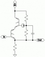
Ah! Here it is...I got home too late last night to think about it. And did other stuff all day today. This isn't a huge swingin' diffy stage, but it can use a lot of different cheap tubes, and only needs one per channel. Nothing about the circuit is really set in stone, all kinds of customizabiliity, this was just one setup i got to test so far...
Attachments

G'Day Tubelab!
Browsing through these pages, daydreaming about future projects...
I really enjoyed the SimpleSE build and was thinking of a suggestion for your PC boards. When I built the SimpleSE, I used the PC board as a template to drill all of my holes. This was fine, but marking out the exact centres of the valve holes was a little tricky. As the valve sockets are fixed to the PC board, there is a lot less room for fudge than a point to point build. I was thinking that if there are no other overriding considerations, maybe a small hole on the PC board at the centre of the valve sockets would make the process of marking out the chassis using the board as a template easier and more accurate for builders.
Just a suggestion, if it is not practical or just plane stupid, feel free to ignore 😉
Cheers!
Chris
I have PDF's of both PC boards to use as a template. They are too big to post here, and I can't figure out how to put them on the web site using my old site builder software. A new web site is in the works using new software, but it is slow going. I am far better with electronics than I am at software and web design.
If anyone wants them, send me an email and I will reply with the PDF's. Print it, tape it to the chassis, and drill (or center punch) right through the paper.
If anyone wants them, send me an email and I will reply with the PDF's. Print it, tape it to the chassis, and drill (or center punch) right through the paper.
Boris_The_Blade said:Ah! Here it is...I got home too late last night to think about it. And did other stuff all day today. This isn't a huge swingin' diffy stage, but it can use a lot of different cheap tubes, and only needs one per channel. Nothing about the circuit is really set in stone, all kinds of customizabiliity, this was just one setup i got to test so far...
hey-Hey!!!,
Nice work there! Can you re-measure with the gate cap moved from ground to the cathode node? ( keeping gate-cathode voltage more like constant )
cheers,
Douglas
Bandersnatch said:Can you re-measure with the gate cap moved from ground to the cathode node? ( keeping gate-cathode voltage more like constant )
Yup, surely can. I think it's still on my bench, so it shouldn't take long. I had also plans to test with a 6H30 next, just waiting for tubes in the mail (courtesy of jon who's eagerly waiting for results 🙂 ).
In response to chrish. I plopped my PCB on a photocopier and made a few copies to use as a template. I taped it to the chassis and then just drilled right though the paper! I was able to make sure the punches were in the right place too. Perfect fit the first time.
- Status
- Not open for further replies.
- Home
- Amplifiers
- Tubes / Valves
- "magic" phase splitter for SimpleP-P