In my scarce spare time I have been researching circuitry for a SimpleP-P amp design. There will be more than one SimpleP-P amp, but I am working on the "little guy" first. This is a small low cost amp aimed at blowing some other low cost P-P amps out of the water. There are several compromises required for any low cost design.
Obviously reducing the number of tubes is a big one. As is a good low cost power supply. It would be possible to make an amplifier with 4 tubes (2 per channel) by using a pair of dual tubes. I built a few. After lots of testing, I came to the conclusion that I wanted to use a pair of "real audio" tubes in the output stage. This means that I would use a solid state power supply, and I needed to design an input stage with enough gain to drive the output stage (30 volts P-P) and allow for the use of negative feedback in pentode mode. I need to get a gain stage and a phase splitter in a single tube to avoid an 8 tube amplifier. No expensive tubes are allowed, and I would prefer a circuit that could use several different low cost tubes without readjustment.
I have always been a fan of the LTP phase splitter, especially with a CCS in the tail. I built at least a dozen of them, and tweaked, tested, and tweaked some more. The only tube that had almost enough gain is the 12AX7 and I am not going there. I want the two outputs to be mirror images of each other out to 100KHz, and the 12AX7 won't do it. The 12AT7 does, but the gain is a little short. There were a few notable circuits, and a few cool ideas that will be looked at for future designs, but they don't fit in here. Look at the "choke tail pair" mentioned here, and try it with a CCS (or a PowerDrive circuit) instead of each plate load. The Hammond 156C choke that I used has 4.3 K ohms of DCR requiring a negative voltage, and there was some phase shift in the upper audio range, but it would be cool with a good choke.
http://boozhoundlabs.com/bhl-15/
OK, I had to pass on the LTP. I tried several of the usual concertina based phase splitters driven by a common cathode gain stage using the other half of a dual triode. These work well, and are the standard choice for this type of amplifier. The typical dual triode that works well here is the 12AT7 or 12AY7. These tend to cost at least $7 USD from most tube sellers due to their "audio tube" status. Others that work well (2C51-5670) may not be easilly available worldwide.
Next, I thought about the triode - pentode tubes used in TV sets. I tried using the pentode for the input stage, and the triode for the concertina splitter. Tons of gain, balance, I am on the right track, but the distortion is a little too high, and the DC voltages change a bunch when I change tubes. Time for some serious tweaking.
The breadboarded circuit was sitting on the bench feeling ingored and neglected for about two months when I saw this thread:
http://www.diyaudio.com/forums/showthread.php?s=&threadid=119821
The little wheel inside the brain started slowly turning. Yes, I tried connecting the screen grid to the cathode of the concertina. I had already guessed what would happen, and I was right. The current drawn by the screen just killed the balance of the concertina. Wheel turning slightly faster, digging through notes..... Then I found the notes that I had made during the experiments done related to this thread:
http://www.diyaudio.com/forums/showthread.php?s=&threadid=97384&highlight=
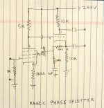
The wheel spun fast enough to light the light bulb in the brain. I could use a mosfet for isolating the screen grid from the concertina cathode. I could also seperate the DC and AC feedback and use a different amount of each. I added the mosfet today and tweaked it out. This was the magic phase splitter circuit. The distortion was in the 0.2 to 0.35 range at 30 volts P-P. The frequency response was very good (-3db at 250 KHz) and the circuit remained balanced beyond the range of my measurement capability. I swapped in a bunch of different tubes, not just different tubes, but different types of tubes. The distortion remained low for all tubes except the 6U8. It would work with a different cathode resistor. Tubes tried: 6U8 - ECF82, 6EA8, 6BL8, 6JW8, 6GH8, 6HL8, 7687, 6KD8, ECF80, and ECF802. Multiple tubes of each type were tried, all worked.
I plan to experiment further with this circuit, but for now I have to work on some TubelabSE issues (2SK2700 replacement evaluations).
Obviously reducing the number of tubes is a big one. As is a good low cost power supply. It would be possible to make an amplifier with 4 tubes (2 per channel) by using a pair of dual tubes. I built a few. After lots of testing, I came to the conclusion that I wanted to use a pair of "real audio" tubes in the output stage. This means that I would use a solid state power supply, and I needed to design an input stage with enough gain to drive the output stage (30 volts P-P) and allow for the use of negative feedback in pentode mode. I need to get a gain stage and a phase splitter in a single tube to avoid an 8 tube amplifier. No expensive tubes are allowed, and I would prefer a circuit that could use several different low cost tubes without readjustment.
I have always been a fan of the LTP phase splitter, especially with a CCS in the tail. I built at least a dozen of them, and tweaked, tested, and tweaked some more. The only tube that had almost enough gain is the 12AX7 and I am not going there. I want the two outputs to be mirror images of each other out to 100KHz, and the 12AX7 won't do it. The 12AT7 does, but the gain is a little short. There were a few notable circuits, and a few cool ideas that will be looked at for future designs, but they don't fit in here. Look at the "choke tail pair" mentioned here, and try it with a CCS (or a PowerDrive circuit) instead of each plate load. The Hammond 156C choke that I used has 4.3 K ohms of DCR requiring a negative voltage, and there was some phase shift in the upper audio range, but it would be cool with a good choke.
http://boozhoundlabs.com/bhl-15/
OK, I had to pass on the LTP. I tried several of the usual concertina based phase splitters driven by a common cathode gain stage using the other half of a dual triode. These work well, and are the standard choice for this type of amplifier. The typical dual triode that works well here is the 12AT7 or 12AY7. These tend to cost at least $7 USD from most tube sellers due to their "audio tube" status. Others that work well (2C51-5670) may not be easilly available worldwide.
Next, I thought about the triode - pentode tubes used in TV sets. I tried using the pentode for the input stage, and the triode for the concertina splitter. Tons of gain, balance, I am on the right track, but the distortion is a little too high, and the DC voltages change a bunch when I change tubes. Time for some serious tweaking.
The breadboarded circuit was sitting on the bench feeling ingored and neglected for about two months when I saw this thread:
http://www.diyaudio.com/forums/showthread.php?s=&threadid=119821
The little wheel inside the brain started slowly turning. Yes, I tried connecting the screen grid to the cathode of the concertina. I had already guessed what would happen, and I was right. The current drawn by the screen just killed the balance of the concertina. Wheel turning slightly faster, digging through notes..... Then I found the notes that I had made during the experiments done related to this thread:
http://www.diyaudio.com/forums/showthread.php?s=&threadid=97384&highlight=
The wheel spun fast enough to light the light bulb in the brain. I could use a mosfet for isolating the screen grid from the concertina cathode. I could also seperate the DC and AC feedback and use a different amount of each. I added the mosfet today and tweaked it out. This was the magic phase splitter circuit. The distortion was in the 0.2 to 0.35 range at 30 volts P-P. The frequency response was very good (-3db at 250 KHz) and the circuit remained balanced beyond the range of my measurement capability. I swapped in a bunch of different tubes, not just different tubes, but different types of tubes. The distortion remained low for all tubes except the 6U8. It would work with a different cathode resistor. Tubes tried: 6U8 - ECF82, 6EA8, 6BL8, 6JW8, 6GH8, 6HL8, 7687, 6KD8, ECF80, and ECF802. Multiple tubes of each type were tried, all worked.
I plan to experiment further with this circuit, but for now I have to work on some TubelabSE issues (2SK2700 replacement evaluations).
Attachments
George, this is intended in a purely constructive manner. There is no doubt that you are more knowledgeable than myself. This is purely a point of view.
30Vpk-pk doesn't seem hard to achieve unless your aiming for input sensitivity, or planning to use a large amount of feedback. Most sources will put out a good 2V. Some amps lack volume range from being overly sensitive and the amp will start clipping with the knob only 1/3 of the way up. It can be slightly frustrating from an end-user point of view.
I have nothing against Pentodes as I use them often, but think 12AT7 may work well. They can be a little pricey if bought new from a supplier, but are widely available and can be scored cheap from ebay.
If you do go with a pentode-triode tube, I'd stay away from the phase splitter-to-G2 feedback. Since you will probably be using Pentode output tubes, the feedback would be better used with the output stage in the feedback loop. And for a "simple PP" using 2 feedback loops wouldn't be so simple. A partially, or fully bypassed cathode resistor with feedback to the cathode of your gain stage would probably make the most sense. That would also avoid loading the plate and cathode of your phase splitter unequally (even tough the Zout is different, something just doesn't feel right about unequal loading), and leave the FET out of it, for the potential builders who want all-tube audio circuitry.
I am always interested in trying some new idea to see what might be discovered. Perhaps something great, or maybe not. Who knows without experimentation? I am really curious, what do you have in mind for output valves?
Wade
Wade
George, this is intended in a purely constructive manner.
Hey, all opinions are welcome and nothing is cast in stone yet. I am throwing this circuit out there in case anyone wants to experiment with it. There is still a LTP breadboard, and a conventional common cathode feeding a concertina breadboard on my bench right next to this one. There will probably be a few more before I am done.
My usual design methodology will create a few different input stages, and an output stage or two, then I will put them together to see what works best as an amplifier using bench supplies and finally design a power supply for it all.
If you do go with a pentode-triode tube, I'd stay away from the phase splitter-to-G2 feedback.
The DC feedback is needed to stabilize the operating point accross a wide variety of tubes. The AC feedback may or may not be used depending on how much gain is needed in the total amp design. I plan to allow for a reasonable amount of GNFB when the output tubes are operated in pentode mode, and allow for zero GNFB for triode mode. I would like there to be enough gain to make full power with a 1 volt signal when max feedback is used. I agree that too much gain is not a good thing, and I am not one to use large amounts of feedback.
what do you have in mind for output valves?
The only choices from a cost and availability standpoint seem to be either the 6BQ5 / EL84 or the 6AQ5 / EL90. The 6AQ5 / EL90's are cheaper and there are plenty of NOS tubes around over 1 million of these were produced. They sound good too, like a baby 6V6 (which is what they are). A breadboard for each will be constructed and tested using a transformer phase splitter. The decision will be made once I start connecting input stages up to output stages and testing and listening to each possibility. The total amp cost is a factor as well.
Another P-P amp is planned using octal output tubes and a far less cost constrained design.
The DC feedback is needed to stabilize the operating point accross a wide variety of tubes.
Interesting idea, I hadn't looked at it that way. If it works right that’s quite ingenious.
The DC + AC g2 feedback scheme may do well in an application where the second stage is a cathode follower too.
The screen feedback approach (or upper grid for cascodes) opens a whole new area for design. Pentodes can now be seen as triodes with separated output and feedback terminals. So much more flexible than triodes.
One does need to keep the plate V above the screen voltage to avoid screen current distortion and preferably both V tracking too. Any of the follower type feedbacks from the plate will do this fine and the resistive divider gives a nice gain boost as well as dropping the screen voltage from the plate V. Should work nice for a splitter as long as the Mosfet is low input capacitance.
With a cascode instead of the pentode, could probably just use the Mosfet follower as the splitter itself, since the upper cascode grid would not be drawing any appreciable current. But this would eat up B+ headroom badly with the cascode unless a zener/cap gets popped in to lower the splitter drive.
Supertex makes some low input capacitance, HV Mosfets, a bit pricey though. VN0550N3 VP0550N3 TN2540N3 TP2540N3
Don
The 6aq5 I think would be fine choice, considering all the cheap stockpiles out there. 6005's, 6095's, etc. I've been thinking how nice it would be if I could swap 6aq5's and 6bq5's whenever. Perhaps a 7pin socket could be mounted on a small PCB adapter that could either plug into a 9 pin socket or solder onto the PCB?
It would be fun to put some lonely 6GH8, 6KT8, 6AN5, etc back to work. I'm all for odd tubes.
It would also be nice to have the option to bias tubes individually. That way matching won't be an issue. The circuit may get a bit more expensive, but the tubes could be any mish-mash. Mish-mash tubes are cheaper too.
It would also be nice to have the option to bias tubes individually.
I'm thinking cathode bias with a balance pot, but I haven't got that far yet. I have about 200 6AQ5's some new, some used, and some very used. There will be plenty of mish-mash to test with. I have some of the cheapest Edcor OPT's and some UTC's and several in between. I have a $22 power transformer solution and some conventional power transformers that cost more. I want the board to work with all of it. As with the SimpleSE some users will want the cheapest possible amp, while others will go for some upgrades.
Maybe transformer phase splitting? Maybe you can use those cheap toroid power transformer. And those with a bigger budget can use proper input transformer. Here is a thread where cheap toroids are used successfully, as both input and output transformers.
http://www.diyaudio.com/forums/showthread.php?s=&threadid=42259&perpage=50&highlight=&pagenumber=1
http://www.diyaudio.com/forums/showthread.php?s=&threadid=42259&perpage=50&highlight=&pagenumber=1
Supertex makes some low input capacitance, HV Mosfets, a bit pricey though. VN0550N3 VP0550N3 TN2540N3 TP2540N3
Don't know where you are shopping but Mouser sells those last few for less than $1 each. This thread is good timing, I am starting to look at designs for a small pentode PP amp.
Maybe transformer phase splitting?
That was ruled out early on. I must design this amp so that it can be built by people of widely varying skill levels all over the world. Many users want to assemble an amp from an exact parts list and do not have the ability to pick out a suitable low cost transformer.
I have done some experiments using budget toroids for OPT's. As anyone who has tried this can tell you, there are plenty of variables, and the results can vary from excellent to nasty.
"Don't know where you are shopping but Mouser sells those last few for less than $1 each."
Yeah, I was looking at the Mouser prices. These Supertex parts are just TO-92 parts, 1 Watt. I'm used to $0.03/100 for BC550 TO-92 bipolar parts.
You can get the Fairchild FQNL1N50B Mosfet for $0.34/100 which is similar to the Supertex parts. But has 115 pF Cinput instead of 45 pF Cinput. And then there is the FQP1N50 which has the same 115 pF Cinput spec, but 40 Watts, for $0.50/100 (which by the way, I measured the input C on a batch of them and they were 85 pF) So one is paying a noticeable premium for that 45 pF Supertex spec.
Don
In a source follower the "reverse transfer capacitance" (gate to drain) is the important spec. The "input capacitance" (gate to source) is bootstrapped by the follower action and does not do much damage.
There are valid reasons (phase intermodulation distortion) to look for a reverse transfer capacitance that remains constant with varying voltage. Most mosfets have a capacitance VS voltage curve buried in the spec sheet somewhere. For many the reverse transfer capacitance flattens out in the range of use for tube amps. The clear winner here is the Toshiba 2SK3563. The curve is a constant 7 pF at any voltage above 20 volts. I have just acquired a bunch of these for testing in a TubelabSE, and one of these was used in the phase splitter experiment.
The Fairchild FQP1N50 is also a good candidate, but this guy really likes to oscillate. It may oscillate only on signal peaks leading to some weird sounding distortion.
Tubelab...Looking at that sketch/photo It looks doubtful if you are doing anything new here.
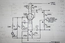
It reminded me of a close-to by RCA with the 7199 application notes (www.triodeel.com/7199.htm).A stab at the data sheet depicts optimising g2 as mission impossible.
I found this RCA circuits esp the g2 of the pentode section requires a totally different voltage than the cathode follower section of the concertina for optimum min thd v.s level.
The black anode originals (at a price!) are fairly consistent and work as enclosed photo cct, but plugging in a Sylvania the repeatable performance becomes choatic. However, when all NOS pentode sections are config as triodes, then things become far more consistent, even Sowteks are fine.
Although I've been thinking on the same lines, sadly the transconductance is a far from a set parameter. So I'm staying with pentode botched as triode front ends. Gain low so I use a step-up transformer.
richj
Attachments
Rich:
Interesting to see a diagram so close to the present screen feedback from a concertina. But it looks to me like C1 (from screen to cathode of the pent.) is an electrolytic since it has polarity signs. I think RCA's engineer was just taking advantage of the convenient voltage source for the screen here. What appear to be voltage markings on the diagram also indicate that it would be in a rather distorting mode with the idle plate voltage at 77V and the screen at 85V.
But I wouldn't be surprised if some old journal article somewhere explored the screen feedback scenario. Not rocket science really. I just don't think that it was making good sense back then without low cap. Mosfets for easy followers.
---------------------
That Toshiba part looks nice too (35 W, 500V, Crss 7 pF typical, but Ciss at 550 pF is a bit high). That flat Crss curve is most likely due to their using a log scale on the capacitance graph, everyone else uses a linear scale for the capacitance axis. Transconductance is the same as the FQP1N50 part when converted to the same current. So it may be an oscillator too. (surface mount gate stoppers)
For comparison on the Crss, the VN0550 is at 2 pF typical and the FQP1N50 is at 3 pF typical (25V)
Don
Tubelab...Looking at that sketch/photo It looks doubtful if you are doing anything new here.
You know, I have that schematic but forgot about it. People have been saying that all possible tube circuits have been invented already. I am beginning to think that this may be true. I spent some considerable time making cathode followers that used a DSP based SMPS to "modulate" the plate voltage to keep the voltage across the tube constant. I thought that it was actually something new until I found out about Macdonalds work with "augmented cathode followers" in 1957. Maybe all possible circuits were invented years ago, but we have technology and components available to us today to reinvent them in an improved way.
But it looks to me like C1 (from screen to cathode of the pent.) is an electrolytic since it has polarity signs. I think RCA's engineer was just taking advantage of the convenient voltage source for the screen here.
Actually it is the DC feedback to stabilize the operating point that I was looking for initially. I have a 1uf cap there which limits the response to essentially DC. The resistor in series with the cap can be adjusted to add some AC feedback if desired to lower the gain. The mosfet is there to avoid loading the cathode, but it may be eliminated if the screen voltage is low enough compared to the plate voltage so the screen draws little current.
Thanks for the warning about tube repeatability. This circuit will remain idle for the next two weeks at least. After that I can run several hundred tubes of various types and conditions through it to see how well it really works with different tubes.
Annoying and critical that even minor diversion of the screen volts on a bench mock-up quickie has such a marked influence on thd. That's what the RCA engineers show with their 7199 data sheets..I 'm well aware that with an amp global nfb thrown in with the complete circuit in a 3 or 4 stage amp the whole trick with linearisating the pentode front end is so nicely accomplished in such a way that it makes the 1st stage screen volt variation a complete hoax. To prove this, I fitted a pot into the screen of the 7199 and adjusted it nearly a 1/3 and amplifier thd remained the same.
Le Nub ?
Perhaps all along I should have been drinking less wine and looking more sober at the whole mathematical feedback equation (nasty) not just only the 1st stage. So things are a bit more complicated than one thinks.
Ironically, substituting an ECF80 into a circuit designed for 7199 with some bits and pieces surgury, the peformance is strikingly similiar! Perhaps a touch more microphony.
richj
How's the Simple P-P coming?
Hi George,
I finally made my first foray into tube amps with a Lafayette 224a integrated amp. Hopefully will arrive this week.
I also closed on my new house finally which means I know have room for HOBBIES!
I was wondering how things are going on the Simple P-P design? I am still very interested in building my own P-P amp and since I have read and heard so many good things about your SimpleSE, I am still convinced that I will build a Simple P-P when it is available.
Keep up the good work. Simple folk like me need people like you who know stuff and can help get us where we want to go.
--Steve
hey-Hey!!!,
I like the looks of your effort Sir Tubelab. I suppose the simple and inexpensive are treated roughly as synonomous here? One does not require the other, but it seems like that is the way you're using it.
Is this PP amp to be Class A, or are you stepping into the max-power sort of AB1 stuff that gave the whole topology a bad rep in certain circles? I'd advocate class A since its applied load is more nearly constant than the a-a/2 to a-a/4 transition at cutoff.
cheers,
Douglas
hey-Hey!!!,
Try the LTP with the same tubes you're using for finals. So you'd need a hugely expensive quad of 6005's per amp...heh-heh-heh.
cheers,
Douglas
Try the LTP with the same tubes you're using for finals. So you'd need a hugely expensive quad of 6005's per amp...heh-heh-heh.
cheers,
Douglas
- Status
- Not open for further replies.
- Home
- Amplifiers
- Tubes / Valves
- "magic" phase splitter for SimpleP-P