I have posted an updated copy of the LXmini article, correcting qty error on the part list, and also put up the list of vendor/part numbers.
FIRST WATT

FIRST WATT
Last edited by a moderator:
How far will the little wonder drive a signal. Put another way how long a cable could I use to the amp or maybe Evan amps.
The output impedance is a bit under 100 ohms, and it will source 1ma
without a lot of distortion.
without a lot of distortion.
I have bought the board with transistors from the store and assembled simple crossover circuit inspired by b5 from slot loaded open baffle project. Works great, nice open sound.
Thanks Nelson.
Question. The kit I received had 17 transistors instead of 16. Am I supposed to return the spare? 🙂
Thanks Nelson.
Question. The kit I received had 17 transistors instead of 16. Am I supposed to return the spare? 🙂
Question. The kit I received had 17 transistors instead of 16. Am I supposed to return the spare? 🙂
I find it easier to error with too many than too few.

I find it easier to error with too many than too few.
Hi Nelson, ok, thanks. I am relieved I do not have to ship it to you or ZM. That was not real question. Here is one.
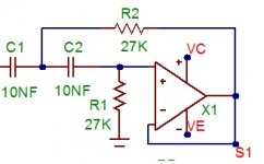
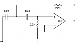
In the typical 12dB/oct filter, there are two caps and two resistors per section. Like here in the pictures. Stolen from late SL page, great site, or your SLOB article.
Attachments
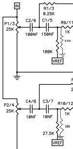
well , I did not follow this thread closely , so not knowing all details ...... but - when you see Pa marked Vref , be sure that he arranged all necessary parts where Vref actually is
Hi everybody,
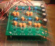
I just built two of the boards, each of them as 24 dB Linkwitz-Riley crossovers. I cascoded them in order to get an active three way crossover. I calculated standard Salley Key with Q=0.71 each. Did not make any fr measurements yet but can already say it does not sound wrong. I used mainly polypropylene filmcaps, some of them are mounted on the bottom side.
I am just curious, across R13 and R15 I get only 0.5 V, while across R14, R16 and R35--R38 I get 0.75 V as expected. This is the first stage where I changed the original circuit to salley key low pass. Should I care about it?
Thank you for this nice little project!
Attachments
Last edited:
V_ref is (virtual) ground for the filter, so there is nothing to worry there. This is because of the single voltage power supply.
But I recognised that the values of the hi and lo pass in the lxmini filters are not the typical sallen key values where you have 2R to ground (or v-ref) in the high pass and 2C in the feedback loop of the low pass. In the LX mini filters this is not as expected. Is it because they are no standard 12 dB filters?
But I recognised that the values of the hi and lo pass in the lxmini filters are not the typical sallen key values where you have 2R to ground (or v-ref) in the high pass and 2C in the feedback loop of the low pass. In the LX mini filters this is not as expected. Is it because they are no standard 12 dB filters?
It is rare when a standard SK filter value is the best fit. That is why I have so much fun with really variable crossovers.
Your top filter is a high Q bass booster, set to provide the EQ on the LXmini low end (more or less).
The bottom is more conventional, but still has some variation of SK reflecting the response curve that SL used in DSP.
Your top filter is a high Q bass booster, set to provide the EQ on the LXmini low end (more or less).
The bottom is more conventional, but still has some variation of SK reflecting the response curve that SL used in DSP.
Last edited by a moderator:
V_ref is (virtual) ground for the filter, so there is nothing to worry there. This is because of the single voltage power supply.
But I recognised that the values of the hi and lo pass in the lxmini filters are not the typical sallen key values where you have 2R to ground (or v-ref) in the high pass and 2C in the feedback loop of the low pass. In the LX mini filters this is not as expected. Is it because they are no standard 12 dB filters?
Ok, makes sense. What about in low pass filter section. Vref resistor remains to provide half the volts (virtual zero), but cap to the ground is missing then.
Thank you Nelson for the reply, I see your point. My speaker chassis have quite flat response so for me standard LR filter works ok (proven before with minidsp).
Can you or anyone else comment on the voltage across R13 and R15 or do you need to see my filter schematic first?
Can you or anyone else comment on the voltage across R13 and R15 or do you need to see my filter schematic first?
@ Nelson
Please share more information on the turn on/turn off thump. Is it a single 0.5 Hz half cycle or does it ring for some time? How much delay would be appropriate for turn on and turn off?
The reason I am asking is that I have the opportunity to power your board from the power amp transformer and through an existing linear regulator, but I don't want to leave the power amp on all the time. I am trying to decide if its worthwhile to come up with some delay circuit, use me as the delay switching the crossover separately, or just go for the wall wart.
Thanks,
Jac
My $0.02 -
Get the recommended wall wart and just leave the crossover on. It's quiet, inexpensive and works great.
Get the recommended wall wart and just leave the crossover on. It's quiet, inexpensive and works great.
That's definitely the fall back position, but I admit that I already have too many "always on" devices in my home and adding another 15 kWhr per year seems wasteful. Of course, that is way better than leaving the power amp on.
Anyway, I'm just trying to understand the issue better and try to be a bit green if I can.
Jac
Anyway, I'm just trying to understand the issue better and try to be a bit green if I can.
Jac
You can always put relays at the output if you are concerned. I have an
easy circuit for slow-on / fast-off relay driver.
easy circuit for slow-on / fast-off relay driver.
- Home
- Amplifiers
- Pass Labs
- LX-mini Crossover Article