Gain is not a problem, there is the volume pot in output. Attenuator + Buffer has the sole purpose of lowering the voltage at the input of the VFET. This stadium is however excludable, and therefore.....
A trasformer with a gain of less than 1 (x0.7) is at the input of the amp. Unfortunately there is no place in the pre.
A trasformer with a gain of less than 1 (x0.7) is at the input of the amp. Unfortunately there is no place in the pre.
Why not put a 25K volume pot at the buffer input and a 5K resistor at the preamp output as suggested by MR? You would then also have a constant low impedance output.
Gain is not a problem, there is the volume pot in output. Attenuator + Buffer has the sole purpose of lowering the voltage at the input of the VFET. This stadium is however excludable, and therefore.....
A trasformer with a gain of less than 1 (x0.7) is at the input of the amp. Unfortunately there is no place in the pre.
Ah, I see. 🙂
whatever
deliberately tossing away any percent of input swing , with resistive attenuator , is perfect way of killing it
classic resistive volume attenuator is another thing - you must have it ........ in most cases
if you want better behavior of VFet regarding input amplitude (THD?) , find another solution ......
anyway, your decision is only yours, I'm/we are just talking of some different side of coin, being informed is best way to make best compromise
Sorry I'm late, I hope Google Translate will assist me!
I share the objections, but.....
Let's try to calculate with the simulator the current in the mesh with R14 and R18. With 1 Vrms in input on R14 there is 40 uA flow. A very low current. Electrons have enough "thrust" to do their home work. If R4 and R14 are a pot, will the current be enough to make the electrons "jump" from the resistive layer to the pot corsor? They are two very different materials. Maybe someone decides to go back!!!
Now let's try to the same calculation with the pot in output. The voltage on the Sony gate is always 1 Vrms. The current on the sliding contact is much highr. Electrons can "jump" more easily.
The VFET in Luminaria allows to test the pot in output with only one active component.
The next step will be an input and output pot.
In the article it mentioned you can look at figure 2 and see the drain resistance will be about 75 ohms at about 80 0r 90 volts. But I thought the drain resistance would be the drain voltage devided by the drain curent. So looking at figure 2 that looks like about 90v / 60ma won't that = 1500 ohms, what am I doing wrong.
just find Rout calculation for comparative triode stage, apply here and you'll know
I didn't checked , though
I didn't checked , though
In the article it mentioned you can look at figure 2 and see the drain resistance will be about 75 ohms at about 80 0r 90 volts. But I thought the drain resistance would be the drain voltage devided by the drain curent. So looking at figure 2 that looks like about 90v / 60ma won't that = 1500 ohms, what am I doing wrong.
The preceding paragraph in the article stated:
"Another important characteristic is drain resistance, which is the change in drain voltage divided by the change in drain current with the gate-to-source voltage held constant (see Figure 5). It is the slope of the line tangent to the curve at the point of interest (e.g., the operating point)."
So it is not as simple as drain voltage divided by drain current.
I have measured the output impedance of my Luminaria and it is in the 75-80 Ohm range.
woody, 1500 ohms is for DC resistance at -19V bias point.
AC resistance (drain impedance) is "change in drain voltage divided by the change in drain current with the gate-to-source voltage held constant", as MR said. Figure 2 is hard to read, but in this case, we can guess something like 3V divided by 40mA = 75 ohm. If the slope is like fig 3, we can see it more clearly, 10 ohm at 2A, which is also close to actual measured SONY's impedance at 2A.
AC resistance (drain impedance) is "change in drain voltage divided by the change in drain current with the gate-to-source voltage held constant", as MR said. Figure 2 is hard to read, but in this case, we can guess something like 3V divided by 40mA = 75 ohm. If the slope is like fig 3, we can see it more clearly, 10 ohm at 2A, which is also close to actual measured SONY's impedance at 2A.
Last edited:
I have measured the output impedance of my Luminaria and it is in the 75-80 Ohm range.
My test result with similar operation point was about the same as yours. (2SJ28). Low enough to drive Tokin.
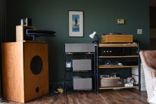
I just finished my LuminAria preamp. It is now in my system and I'm listening to it.
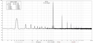
My old preamp was DIY 01A tube based with filament bias and output transformers. I really liked it a lot, but the old tubes are getting harder to find and my stash is running low. I was resorting to using 112A tubes, which are the power version of the 01A. So, it was time to cut my dependence on the old tube market.
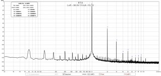
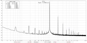
I measured the distortion spectra of the tube preamp using the 112A so that I had a basis for comparison when I got my LuminAria running. I've included FFTs of both the tube and LuminAria preamps for comparison.
I used fixed bias for the Luminaria as several other people have done so. It makes for adjusting the operating points easy.
Now, my amplification chain is totally VFET. I run a biamped system with a 2SJ28 L'Amp 193V for the top end and BAF2015 THF-51S amps for the low end. VFET heaven!
Another great Rothacher design. Thank you, sir.
My old preamp was DIY 01A tube based with filament bias and output transformers. I really liked it a lot, but the old tubes are getting harder to find and my stash is running low. I was resorting to using 112A tubes, which are the power version of the 01A. So, it was time to cut my dependence on the old tube market.
I measured the distortion spectra of the tube preamp using the 112A so that I had a basis for comparison when I got my LuminAria running. I've included FFTs of both the tube and LuminAria preamps for comparison.
I used fixed bias for the Luminaria as several other people have done so. It makes for adjusting the operating points easy.
Now, my amplification chain is totally VFET. I run a biamped system with a 2SJ28 L'Amp 193V for the top end and BAF2015 THF-51S amps for the low end. VFET heaven!
Another great Rothacher design. Thank you, sir.
Attachments


Last edited:
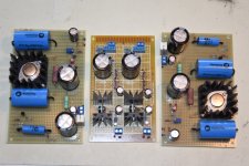
I did something similar to this project with "fake SIT" technology and cascoded current source loading. i used it as the lineamp stage for a combined hybrid RIAA/lineamp all-in-one board. I've yet to put the thing in a box, though it measures OK on the bench. I want to clean up the DC-DC converter that powers it before I load it into a box and do some listening tests. The board can be viewed here...
Hybrid RIAA/Line Amp
Hybrid RIAA/Line Amp
Last edited:
Now, my amplification chain is totally VFET. I run a biamped system with a 2SJ28 L'Amp 193V for the top end and BAF2015 THF-51S amps for the low end. VFET heaven!
Another great Rothacher design. Thank you, sir.
Great!
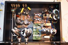
I've been listening to my LuminAria for about a week and I am not missing my 01A tube preamp at all. One thing I really don't miss at all is the tube noise, the hiss and slight hum. The LuminAria is dead quiet even with my fairly efficient speakers. I can't hear a thing with my ear right up against the speakers.
When I measured the LuminAria's distortion last week, I noticed that the right channel was noisier than the left. Even though it was not apparent when listening to music, it bothered me. That's the problem with measurements, sometimes.
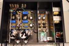
So, after analyzing the situation, I decided to relocate the two large transformers and add some shielding. I installed 22 gauge mild steel sheets between the transformers and the power supply boards, and also between the power supply boards and the preamp boards.
As a result, the 60 Hz and harmonics have decreased greatly on the right channel, although it is still noisier than the left. However, I'm not going to worry about it anymore. Time to listen to more music.
When I measured the LuminAria's distortion last week, I noticed that the right channel was noisier than the left. Even though it was not apparent when listening to music, it bothered me. That's the problem with measurements, sometimes.
So, after analyzing the situation, I decided to relocate the two large transformers and add some shielding. I installed 22 gauge mild steel sheets between the transformers and the power supply boards, and also between the power supply boards and the preamp boards.
As a result, the 60 Hz and harmonics have decreased greatly on the right channel, although it is still noisier than the left. However, I'm not going to worry about it anymore. Time to listen to more music.
Attachments

Great info! I have a pair of 2sk82 and want also to make a nice pre amp. I am just wondering do you have gerber files available? Thanks!
- Home
- Amplifiers
- Pass Labs
- Luminaria?