I think there is a way to take two of these using a common choke, and have them driven by a balanced preamp and drive them in bridged output for 150w. Plus, double the slew rate. That would be interesting.
Very interesting! For reasons I do not understand I am thinking of a tube front end with a bit of gain. 😀
For reasons I do not understand I am thinking of a tube front end with a bit of gain. 😀
Well, that is not an unreasonable thought! 😀
@mbrennwa,@zman01
Indeed, the choices are endless.
Last night I was looking at the AMB B22 which is a superb headphone amp and linestage full of Class A discrete goodness. My mind is going in circles

This one I will have to fit into a 4U chassis however given the heat dissipation of the LuFo itself.
Where is the group buy list? 😀
Best,
Anand.
Indeed, the choices are endless.
Last night I was looking at the AMB B22 which is a superb headphone amp and linestage full of Class A discrete goodness. My mind is going in circles
This one I will have to fit into a 4U chassis however given the heat dissipation of the LuFo itself.
Where is the group buy list? 😀
Best,
Anand.
Last edited:
Nope, not unreasonable at all. Although, the raison d’etre of the LuFo is having a SET-like valve harmonic profile whilst using a solid state part capable of controlling massive amounts of current for less than the cost of the socket of a glass envelope valve!
A hybrid approach with a valve buffer driving a HV SS opamp might be the easiest lowest distortion implementation, albeit not a discrete one.
A hybrid approach with a valve buffer driving a HV SS opamp might be the easiest lowest distortion implementation, albeit not a discrete one.
Last edited:
Hello,
I'm very interested in this amp, the is also the possibility to work at half power may be 20W of output power and make a low power and more compact amp?
Do you have done any test?
Are you planning a GB for the PCB's?
Regards
Guglielmo
I'm very interested in this amp, the is also the possibility to work at half power may be 20W of output power and make a low power and more compact amp?
Do you have done any test?
Are you planning a GB for the PCB's?
Regards
Guglielmo
I think there is a way to take two of these using a common choke, and have them driven by a balanced preamp and drive them in bridged output for 150w. Plus, double the slew rate. That would be interesting.
For a balanced version you could use the secondaries of an EI transformer let's say 24+24v the DC currents of both legs should cancel reciprocally and the AC currents summ up... Put the gnd at the mid point and one LU at each +24 and - 24 winding
But then you need a good balanced preamp or 2 separate preamps fed by a balanced DAC
But balanced will cancel second harmonic?
Last edited:
Once I have a chance to listen to an amp subjectively for several days, and I can hear all the things I like or don't like about it, I will then take measurements. The reason I do it this way is so I do not bias my subjective opinion with the data. As I said before, this amp sounds so good - perhaps one of the best amps I have heard. That usually means that it has very low noise, a good 2nd order dominant harmonic profile, and monotonically descending higher orders. It also means that usually, the third harmonic is about -10 to 15dB lower than the second harmonic, and there is very little of higher orders beyond 3rd or 4th at lower powers.
The measurement setup is same as I have used many times in the past: Focusrite 2i4 sound interface operating in ASIO mode, REW software, 10ohm non inductive EBG 300w thin film resistor, and balanced 10:1 signal attenutator for the inputs. This time, since this amp is not an ultra-low distortion amp, I used simply a 1kHz test tone FLAC file played by a high quality digital player (Cayin N3 with AKM4490 DAC). Fluke 101 meter to measure the RMS voltage. I am using the Aksa Lender as the preamp here to get some gain to drive the amp.
Photo of the setup, you can see the heatsinked dummy load resistor in the foreground and the balanced signal attenuator with the two 4.7uF 250v MKP film caps to couple the signal to the audio interface.
Here is 2.83Vrms into 10ohms - we get 0.010% THD and a harmonic profile very similar to predicted for 8ohms. There is a small bump at the 5th harmonic, although very low - this might be a problem at higher powers if it becomes too high. We will keep an eye on it. The noise floor is very low circa -125dB (not including the 60Hx bump) and clean and free of hash. There is a 60Hz bump, but I believe that is just pickup from the EMI in the air. It is still down at -105dB:
Here is 4.0Vrms into 10ohms - we get 0.017% THD:
Here is 8.0Vrms into 10ohms (a quite loud playing level for average music), 0.035% THD and still a dominant second harmonic and lower higher orders. The 5th harmonic here is not a problem as it is just part of a progression of decreasing higher orders harmonics:
This amp measures very well. At this point, I could not do higher powers as my signal generator and preamp combo were not set up for it. So far, it is behaving very closely to the simulation. Looks like the grounding and the choice of PSU made for a very quiet amp as well.
Interesting,the second harmonic in your 1 watt ltspice sim shows a positive phase second harmonic (-92 degrees)yet your rew measurements later on show a negative phase second harmonic (+68 degrees) with a roughly equivalent power ouput into 10 ohms.I wonder why the difference?
I am not quite sure but suspect that the LTSpice FFT phase is off because I did not tell it to take FFT on steady state data. There is an initial startup transient in the time series.
In the measured data, there is some phase contribution from the preamp (SE Class A discrete - based on Aksa-Lender topology). It is dominant second harmonic but I am not sure if positive or negative phase 2nd harmonic.
In the measured data, there is some phase contribution from the preamp (SE Class A discrete - based on Aksa-Lender topology). It is dominant second harmonic but I am not sure if positive or negative phase 2nd harmonic.
I have some contacts in China and will see if I can get a batch of MOTs at wholesale. These are compact but heavy items. They will have to go in shipping container by sea. But need to see what kind of minimum order quantities are. I know that a new, nicely built microwave oven from Guangdong Microwave Oven Mfg Company is only $50US in China. So the MOTs must be like $5 in quantity 100,000! 😀
With a balanced design it would look like Susan Parker's Zeus (Audiophonics -).
Because she used lower transconductance power mosfets (also depletion type IXTH20N50D), the output transformer has a step down ratio.
Another, and one the best commercial solid state amps I auditioned is the Grandinote Shinai, following the same design principle: class A with high power bipolar emitter followers loaded by a center tapped autoformer (no step down). This one does not have output coupling capacitors as the + and - output have the same (low) DC potential.
The same could be done with a pair of LU1014D's (or more pairs...).
To get some 20 watts of output power each LU1014D would have to dissipate 20 watts, no idea if that is realistic as it is a tiny device.
10V supply (only one positive supply needed) and 2A of current you'd reach almost 50% of efficiency.
"Descending harmonic distortion profile" is not a holy grail IMO; distortion profile of the Zeus amplifier looks excellent as well.
Yes the zeus amp exactly it uses non gaped EI transformer because the DC magnetic flux of both windings almost cancels. therefore no need of costly gaped chokes.
latest FFT I could find of the Zeus driven by SE Preamp
Zero Feedback Impedance Amplifiers
latest FFT I could find of the Zeus driven by SE Preamp
Zero Feedback Impedance Amplifiers
I really like Susan Parker's Zeus amp, but it is not the same topology at all. Zeus uses output transformer to couple MOSFET driven primaries to balanced drive output secondaries. LuFo uses transformers as reactive load to increase output swing.
Last edited:
Take a better look; I am talking about the output stage.
The Zeus output stage is inductively loaded to increase output swing and approach the (theoretical) 50% efficiency.
The Zeus output stage is inductively loaded to increase output swing and approach the (theoretical) 50% efficiency.
Here is Susan's explanation of the topology:

Make of it what you will, but I don't see a hot running always-on SE Class A amp with the choke serving to provide reactance to double the output. The output is doubled because it is a balanced (like a BTL) output. The output is transformer coupled not capacitively coupled. Depending on the winding ratios, it could have voltage gain from the transformer.
Maybe if the Zeus was modified to this, it would be similar. This requires:
Neither MOSFET turns off at any time (during normal operation) so there is no Class B bit, however this isn't the same as my understanding of normal Class A operation where lots of power gets disapated all the time.
My amps quiescent is low and the heatsink is correspondingly small, being barely warm to the touch when idle. Of course it warms up a little when in use. The only time it has got seriously hot was when making power measurments and driving full peak to peak sinewaves into an 8 ohm load.
An inportant thing to understand is that the output transformer's primaries swing negative as well as positive and the MOSFET for the half of the cycle which is negative is still powered but "idles" with most of the current flowing through the MOSFET going positive. However the negative arm MOSFET "WILL" regulate if something tries to overrun the main positive arm MOSFET position.
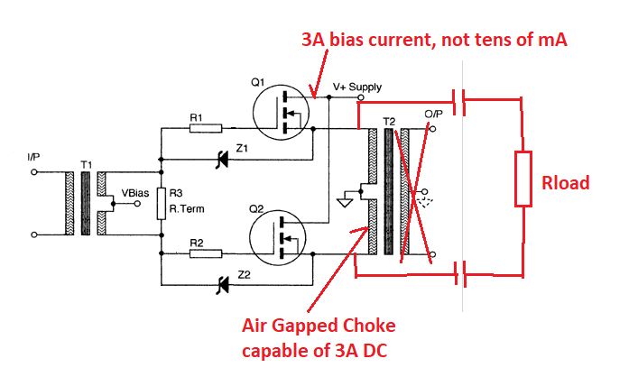
Make of it what you will, but I don't see a hot running always-on SE Class A amp with the choke serving to provide reactance to double the output. The output is doubled because it is a balanced (like a BTL) output. The output is transformer coupled not capacitively coupled. Depending on the winding ratios, it could have voltage gain from the transformer.
Maybe if the Zeus was modified to this, it would be similar. This requires:
- Air Gapped DC Choke with center tap or two regular ones in series with common tied to GND
- Increase bias current to always on 3A vs miniscule tens of mA
- Capacitive coupled outputs at Source of MOSFET not transformer coupled outputs.
Attachments

Last edited:
OK, after you edited:
When making the LuFo balanced, you will use a center tapped choke; the DC currents cancel.
This is exactly how the Zeus output stage functions; no matter whether you bias for class AB or rich class A, the DC cancellation remains and does not make an air gap necessary.
So you could bias a push pull LuFo class AB or whatever.
Instead of output coupling capacitor(s) you could use an output transformer with secondaries; Susan had to (with step down) in order to load the mosfets appropriately.
1014's are very high transconductance so you don't need step down, and then a choke / capacitor combo is an option; 1:1 output transformer would work equally well.
The output coupling cap can be calculated to create the correct high pass when for example driving a tweeter and will be higher quality than the 4700uF or so electrolytic required for full range.
- Home
- Amplifiers
- Pass Labs
- LuFo Amp - 39w SE Class A from 28v Rail