I can’t say that they will be better unless Lundhals have a spec that guarantees they can sustain 3A and still be capable of rated inductance circa 60mH at circa 40Hz.
I guess we will know once Anand builds his LuFo. 😉
I guess we will know once Anand builds his LuFo. 😉
The Lundhal 2773 data sheet says it was designed as a filament heater filter - not really for audio frequencies. So no guarantee it will work better...
Although nominally at 95mH and 0.44ohm DCR, it has a good amount of inductance to start with and designed for up to 3.5A DC.
https://www.lundahltransformers.com/wp-content/uploads/datasheets/2773.pdf
Although nominally at 95mH and 0.44ohm DCR, it has a good amount of inductance to start with and designed for up to 3.5A DC.
https://www.lundahltransformers.com/wp-content/uploads/datasheets/2773.pdf
X,
I can buy and mail it to you to test. But unfortunately, no shipments till September since Lundahl takes a vacay in August per the distributor here.
Best,
Anand.
I can buy and mail it to you to test. But unfortunately, no shipments till September since Lundahl takes a vacay in August per the distributor here.
Best,
Anand.
One aspect that may be contributing is the filament/ps chokes are designed to work on mains frequency so 50hz minimum. There is a difference even between transformers specd to work on 60 hz vs 50/60 hz, so you have to expect earlier saturation at below 50 hz for these chokes.
Have we determined a minimum value for the inductance in these followers? Is it as low as 50 mH? Or do we really want 100 mH? If we are thinking about a groupbuy, we should contact companies who make both audio transformers, plate chokes and high current chokes for prices on custom models that meet the design goals of required inductance at 30 hz (cheaper that 20 hz) and 3.5 amps, while keeping appropriate HF design for a plate choke. Edcor, Heyboer, and Electra-print come to mind. Electra-print will probably be $$$ though.
Edit* I see above we want 60mH at 40 hz. Is that a consensus?
Edit* I see above we want 60mH at 40 hz. Is that a consensus?
Last edited:
I think X’s quote here is highly relevant:
“ If you play bass riff heavy music loudly, choke loaded SE Class A amps may not be the best choice.”
So move your listening position closer, or use more sensitive speakers or both.
My speakers are 96dB sensitive and I use an asymmetrically distributed multi bass system (swarm). It alleviates most bass concerns for me. I am primarily interested in > 50Hz with the amps for my mains.
When used with a digital source, which nowadays put out at least 3V RMS or more another problem is also solved. You don’t need so much gain in your amplifiers and you can do away with preamps altogether.
I am perfectly happy with 14-20dB of overall gain. But my dac puts out 5.8V rms. Even with 4V rms I was perfectly happy. Recordings that are low in volume like Hugh Maskela’s stuff are no problem.
Living with 82-86 dB speakers is difficult if you want to play with “affordable” low power SE output stage topologies! Push pull would be a better choice there. Especially at higher SPL levels.
Looking back at X’s scope measurements, if the impedance was at the worst case scenario of 8 ohms then the 1st scope graph was at 3 watts rms (14Vpp) and second was 24 watts rms (40Vpp) right? That’s a wide range of power levels but it gives us a good idea of what to expect! Thanks!
Best,
Anand.
Last edited:
Hi Anand,
You raise some great points on how to alleviate the deep bass clipping. My speakers are terribly inefficient at 82.5ddB. Just a consequence of baffle step from a nominal 88dB.
Having 96dB sensitive speakers is like having a 14dB more powerful amp
Putting a high pass and a dedicated subwoofer would alleviate a lot of these issues and let a SE Class A amp do what it does best: midrange and highs.
Loud, low bass, efficient. Pick two. The third one will be very non-optimal. Or just look up "the iron rule". Low bass, loud and efficient will be a very large cabinet.
Large front loaded bass horns can be 105dB/W but huge. Reasonably sized tapped horn subs can approach 100dB I think. Still quite large for home use.
Large front loaded bass horns can be 105dB/W but huge. Reasonably sized tapped horn subs can approach 100dB I think. Still quite large for home use.
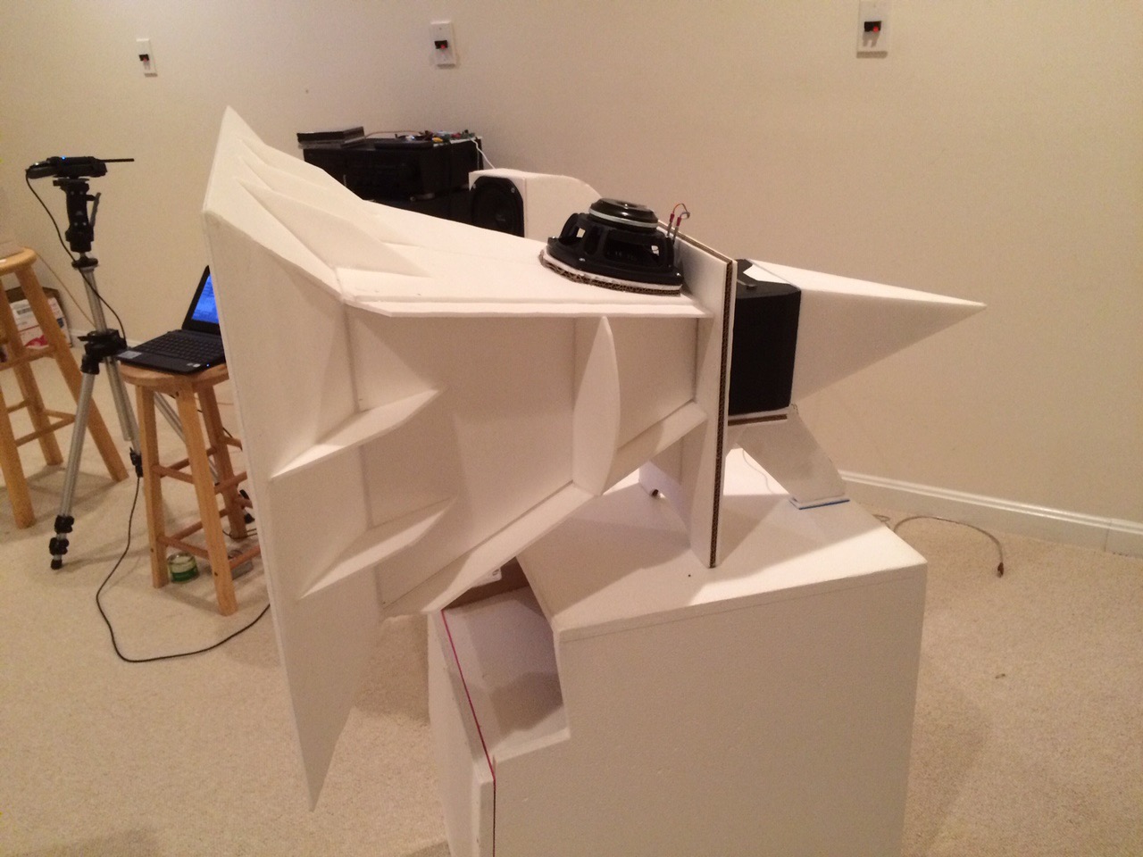
Horns sound "awk-ish" to me. Personal taste. I have designed built and listened to many horn system. To me they sound like horns and not like musical instruments. Bass horns are H-U-G-E. I built a horn that was too large to leave the room it was built in. ah...youth.
When designed based on simulations - and well implemented, horns have always sounded the best to me of all speakers. My quad driver bass horn coupled with a synergy point source horn fitted with a Heil AMT and B&C MDN64 pro mid is still the best sounding speaker I have ever heard.
Last edited:
Synergy horns are very special indeed.
I have fond memories:
https://www.diyaudio.com/forums/multi-way/368860-danley-signature-series-16.html#post6701236
Best,
Anand.
I have fond memories:
https://www.diyaudio.com/forums/multi-way/368860-danley-signature-series-16.html#post6701236
Best,
Anand.
I put an ad up in our local community for microwaves that people no longer wanted. So Far I have 5, ranging from very old to a few years old. I measured them on my LCR to get some rough numbers and this is what I got:
1. 57mH, 0.8 ohms
2. 63.7 mH, 0.5 ohms
3. 125.2 mH, 0.8 ohms
4. 51mH, 0.6 ohms
5. 34.2mh, 0.4 ohms ( this transformer is very very old, so probably will not use).
In 1-4, is there any that I should not use. Thanks for the help.
MM
1. 57mH, 0.8 ohms
2. 63.7 mH, 0.5 ohms
3. 125.2 mH, 0.8 ohms
4. 51mH, 0.6 ohms
5. 34.2mh, 0.4 ohms ( this transformer is very very old, so probably will not use).
In 1-4, is there any that I should not use. Thanks for the help.
MM
Any of the first 4 can work. I would go with 2 and 4 as they have the lowest DCR.
What a great idea to put up an ad. You did the earth a service by recycling/reusing something otherwise would have ended up in a landfill.
We should all do that!
What a great idea to put up an ad. You did the earth a service by recycling/reusing something otherwise would have ended up in a landfill.
We should all do that!
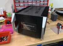
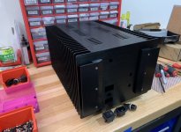
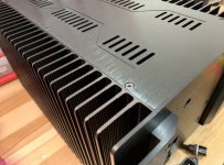
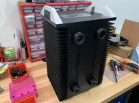
I finally had a chance to assemble the chassis (1 channel). It all fits together precisely and solidly. Very nicely made all CNC chassis. No instructions of course, but easy to figure out. The hardware was nice too. Socket cap screws and black finish bevel Phillips screws for the top and bottom panels. PC board for the VU meter driver. IEC, power switch, and fuse holder included.

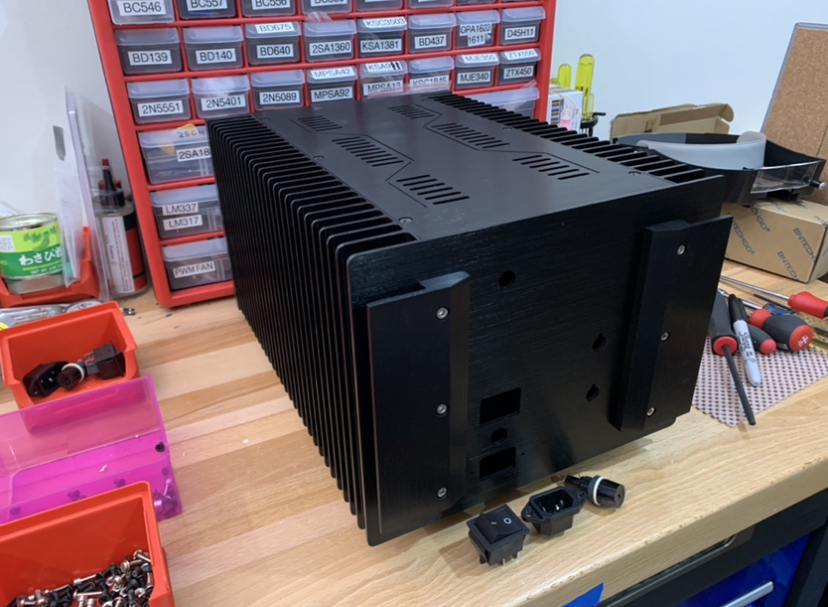
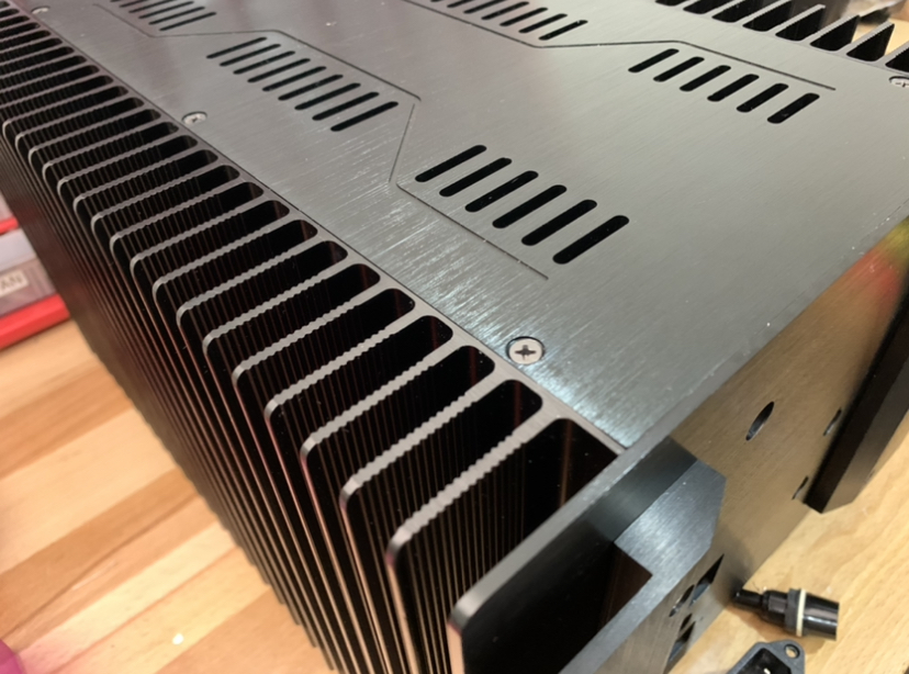

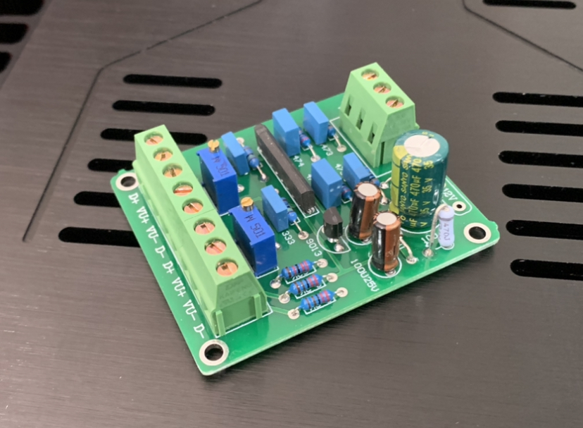
So far so good. Now I need to drill and tap threaded holes for mounting the MOSFETs and LU1014D.
So far so good. Now I need to drill and tap threaded holes for mounting the MOSFETs and LU1014D.
Attachments
-
 502419AE-F3E2-46F8-94BE-68B15F00CDCF.jpeg417.7 KB · Views: 947
 -
 3DB996C5-CC97-4E84-8E7D-FEEBA0E0D117.jpeg460.8 KB · Views: 965
 -
 61EF0EDA-5221-45A3-A353-F3A6EC3544E6.jpeg439.5 KB · Views: 959
 -
 B18FC3FE-E1A9-4137-B785-40DFD152C36F.jpeg447.5 KB · Views: 972
 -
 385D93C3-2B2F-493C-B4D3-7E8DBE4408F3.jpeg363.6 KB · Views: 967
I put an ad up in our local community for microwaves that people no longer wanted. So Far I have 5, ranging from very old to a few years old. I measured them on my LCR to get some rough numbers and this is what I got:
1. 57mH, 0.8 ohms
2. 63.7 mH, 0.5 ohms
3. 125.2 mH, 0.8 ohms
4. 51mH, 0.6 ohms
5. 34.2mh, 0.4 ohms ( this transformer is very very old, so probably will not use).
In 1-4, is there any that I should not use. Thanks for the help.
MM
MM,
These are static measurements with your LCR.
It does not say anything about inductance of these cores in an amplifier with DC current applied!!
With DC current applied, for example the 57mH of your choke 1. might drop to 20mH or so (representing a mere 2.5 ohm reactive load...).
With DC current applied the induction will drop!
You need to measure with DC current applied to judge these chokes for suitability.
Also check my post at the SuSyLu thread.
To get an impression of what is involved in inductance measurement with DC current applied:
Testing Transformers with High DC Bias
Likely the option for this professional measurement is not available to most, so it remains to check how the choke performs in a real amplifier (with the possibility to be faced with the problem X demonstrated, the cause being substantial drop of inductance).
Last edited:
Hi Daanve,
Thank you for your comments and links on details of transformer making and special tool used to measure. That is indeed beyond what a DIY’er can use as that instrument looks quite expensive and designed for professional use.
As a DIY’er can one use the actual amp to measure the inductance under load? One can run sinusoid waveform to excite inductor and measure frequency response. This is a steady state (repetitive cycle) AC test. The problem I saw seems to manifest only occasionally and under specific load of heavy use of bass while simultaneously requiring high amplitude high frequency excursion superimposed on the heavy bass.
So the testing would almost be DC bias current of 3.0A applied, plus 40Hz excitation at say 75% of level before predicted clipping; then superimpose on top of that a low duty clucks 1kHz equivalent pulse burst at some level from low up to where clipping is observed on an Oscope (circa 80%).
Then in a simulation, adjust inductance in model until clipping is observed. Would that work?
- Home
- Amplifiers
- Pass Labs
- LuFo Amp - 39w SE Class A from 28v Rail