Thanks for the kind words X. I also pulled out some of the coil/ferrite moter bushings for the fans, and a lot of the wires with the attached clips on the ends already. The bottoms on some of the ovens can be used for a base of an amplifier. I also pulled the pcb boards to see what could be saivaged.
Thank you daanve for your links and knowledge on this subject. I will read that paper to enlighten myself.
Since I do not have a lab or a lot of sophisticated equipment, I will be using the trial/method system. Since Vunce / X have working model's, I will try to size the MOT's as close as possible, and measure in system. I am not a person who likes excessive bass, so it should work OK. Interesting stuff this is!!!
MM
Hi Myles,
The MOT will work for 99% of the music I listen to. It was just certain tracks with sustained deep bass and highs superimposed that had problems. Most music is not like this and so a MOT, while not technically designed for such duties, will serve a purpose nicely to make good music and save money, while improving the sustainability of the planet. A win win for most people.
The MOT will work for 99% of the music I listen to. It was just certain tracks with sustained deep bass and highs superimposed that had problems. Most music is not like this and so a MOT, while not technically designed for such duties, will serve a purpose nicely to make good music and save money, while improving the sustainability of the planet. A win win for most people.
Hi X,
Since I am waiting on parts, I have the transformer/All C's hooked up. Could I run some power thru the MOT using the variac and a DMM for measuring the current and the LCR for measuring the inductance.
If so, any special precautions I should be aware of.
MM
Since I am waiting on parts, I have the transformer/All C's hooked up. Could I run some power thru the MOT using the variac and a DMM for measuring the current and the LCR for measuring the inductance.
If so, any special precautions I should be aware of.
MM
As a DIY’er can one use the actual amp to measure the inductance under load? One can run sinusoid waveform to excite inductor and measure frequency response. This is a steady state (repetitive cycle) AC test. The problem I saw seems to manifest only occasionally and under specific load of heavy use of bass while simultaneously requiring high amplitude high frequency excursion superimposed on the heavy bass.
Yes, that's why I asked to feed the amplifier with a 20 Hz sinus at full power.
I know that it is a worst case scenario, but when the choke is underrated it will show core saturation, and with severe core saturation the induction will be "zero", only leaving the winding DCR as "load" (you can find somewhere how core saturation looks on the oscilloscope). That way you can also check at which frequency the sinus stays clean; normally, when core saturation starts at 20 Hz halve power (some 9 VRMS for a 39 watt@8ohm amp), core saturation will start at 40 Hz full power (some 18 VRMS), so an octave higher.
In tube amplification, a quality output transformer should be able to remain "clean" at full power @ 20 Hz.
Why not the same approach for a good SS class A amp?
Of course, when you wish to cut cost you choose to do concessions.
Option is, as already mentioned, to relieve the amp from bass duties; for an amplifer working from 50-60 Hz things become much easier.
Last edited:
Hi X,
Since I am waiting on parts, I have the transformer/All C's hooked up. Could I run some power thru the MOT using the variac and a DMM for measuring the current and the LCR for measuring the inductance.
If so, any special precautions I should be aware of.
MM
You can’t use a standard LCR meter to measure while applying high DC bias current. It requires a specialized (expensive) instrument. The only way a DIYer can do this is to measure frequency response under full load (50Vpp output) and 3A current.
As Daanve pointed out, these are the issues of testing at high DC and using a traditional LCR meter.
Testing Transformers with High DC Bias
I have a scope with Bode plot/FRA capability and can determine what the F3 is of the circuit is while running 3+ amps across the choke in the output stage and a 100 watt/8 ohm load resistor. My generator for the scope has only 10V PP capability so I will definitely need a gain stage with it to make the determination. But yes, the best way is to test the choke under real working conditions. Like the Mofo, the choke can definitely be a sonic impasse due to where it lies in the circuit. But unlike the Mofo, 39 watts RMS is very different than 10-15 watts RMS with respect to core saturation at 20Hz. One octave above, i.e. 40Hz is a much easier goal.
Another test, one for which I don’t have the correct device for (yet!) is an audio analyzer (X’s REW setup or equivalent) so we can see how much distortion (THD, IMD, spectra) there is at 20Hz at that max output level.
Best,
Anand.
Another test, one for which I don’t have the correct device for (yet!) is an audio analyzer (X’s REW setup or equivalent) so we can see how much distortion (THD, IMD, spectra) there is at 20Hz at that max output level.
Best,
Anand.
I managed to get off a bit early from work and got several broken microwaves on the way home. Spent a couple hours in blazing heat in the garage to extract the transformers.
Resistance test was using Fluke 8062A
Inductance test was using Sencore LC101
Both testers were not recently calibrated.
Results:
MD-101AMR 0.42ohm 23.9mH
MD-102AMR-1 0.41ohm 24.8mH
MD-102AMR-3 0.40ohm 26.4mH
MD-903AMR-1 0.47ohm 26.3mH
Not too sure whether these are still good for this build.
Resistance test was using Fluke 8062A
Inductance test was using Sencore LC101
Both testers were not recently calibrated.
Results:
MD-101AMR 0.42ohm 23.9mH
MD-102AMR-1 0.41ohm 24.8mH
MD-102AMR-3 0.40ohm 26.4mH
MD-903AMR-1 0.47ohm 26.3mH
Not too sure whether these are still good for this build.
Attachments
Last edited:
Tagheue Testing......
TH,
Were these MOTs from a 220-230 mains?
I suspect they are 120V however.
Not really enough inductance. We need a minimum of 50mH for 8R speakers, and 100mH would be ideal, but such monsters are very large, expensive and heavy.
Thank you for the precious information.
Hugh
TH,
Were these MOTs from a 220-230 mains?
I suspect they are 120V however.
Not really enough inductance. We need a minimum of 50mH for 8R speakers, and 100mH would be ideal, but such monsters are very large, expensive and heavy.
Thank you for the precious information.
Hugh
Last edited:
Nice work TagHeuer!
Those MD-102’s are massive. There’s no way it’s only 25mH unless it’s broken or your LCR is off calibration. Those are all 120v units from the label and as you are in Canada. Did you happen to drive by curbs on trash pickup day?
Extracting them is a b!txh - a lot of sharp corners and sheet metal to deal with.
See if you can get another measure of L - do you have a DATs or a $15 transistor tester with LCR?
Last edited:
Those transformers are 120V.
The Sencore LC101 is primarily used for measuring capacitor leakage and values and so far it has done pretty good jobs.
However it is most likely out of calibration for measuring inductance. Sorry guys for providing inaccurate results.
As for source of those transformers, I was searching local ads from kijiji (similar to craigslist) for free microwave and there were several of them in the area.
Unfortunately I don't have other meters to measure inductance at the moment. I'll see whether I can borrow one from my friends/colleagues.
Last edited:
I really like how people are being creative in trying to obtain MOTs for repurposing as an audio component. The MOTs work quite well for most musical needs. For the cost, it’s hard to complain about them.
Hi X,
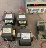
These are my 4 MOT's

From L to R I measured the static inductance and the resistance of each using my transistor tester. I measured the inductance of each MOT until the readings did not vary much.
MOT - Left: 94.73 mH, 1.9 ohms >>> 91.13mH, 1.2 ohms after 25 readings.
Next - 97.33 mH, 0.9 ohms >>> 93.23 mH, 0.9 ohms after 25 readings
Next - 271 mH, 1.2 ohms >>> 261 mH, 1.0 ohms after 25 readings
MOT - Right: 103.9 mH, 0.9 ohms >>> 102.2 mH, 0.9 ohms after 10 readings
From my LCR meter:
MOT - Left: 56.8 mH, 0.9 ohms Next: 51.2 mH, 0.6 ohms Next: 124.8 mH, 0.8 ohms MOT - Right: 63.9mH, 0.5 ohms
Any reason for the difference in the inductance readings from the LCR vs the Transistor tester? Both test units have good batteries. Which one to believe.
I do have a DATS V3 that I could fire up to also check measurements.
Thanks for the help,
MM
These are my 4 MOT's
From L to R I measured the static inductance and the resistance of each using my transistor tester. I measured the inductance of each MOT until the readings did not vary much.
MOT - Left: 94.73 mH, 1.9 ohms >>> 91.13mH, 1.2 ohms after 25 readings.
Next - 97.33 mH, 0.9 ohms >>> 93.23 mH, 0.9 ohms after 25 readings
Next - 271 mH, 1.2 ohms >>> 261 mH, 1.0 ohms after 25 readings
MOT - Right: 103.9 mH, 0.9 ohms >>> 102.2 mH, 0.9 ohms after 10 readings
From my LCR meter:
MOT - Left: 56.8 mH, 0.9 ohms Next: 51.2 mH, 0.6 ohms Next: 124.8 mH, 0.8 ohms MOT - Right: 63.9mH, 0.5 ohms
Any reason for the difference in the inductance readings from the LCR vs the Transistor tester? Both test units have good batteries. Which one to believe.
I do have a DATS V3 that I could fire up to also check measurements.
Thanks for the help,
MM
MM,
The measurements are static.
However, unlike resistors and capacitors, inductances are not constant.
Inductance varies with frequency and amplitude of the test signal (to name the most important variables).
LCR meters measure with small signals like 0.5 V at 100 Hz.
More expensive meters also measure at higher frequencies, for example 1 kHz.
You would measure different inductances at different frequencies (the core looses permeability at higher frequencies).
So in general a measurement only gives a clue of what inductance is available, and as stated before, when DC current is applied the situation is very different again.
Static measurement of inductance is mere speculation.
The only way to check the suitability of these MOTs is putting them in the amp and measure low frequency bandwidth, check for core saturation.
The only useful spec is DCR of the MOT as it biases the LU, assuming that DVM's are accurate enough.
Last edited:
Thanks for sharing those measurements, MM and thanks for the explanation Daanve. If you have a DATS, it's very easy to use, give it a go. That is what I use and it measures it by applying a sweep from DC to 20khz and it plots the impedance and phase. From that impedance plot it figures out some "average" inductance.
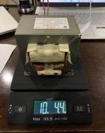
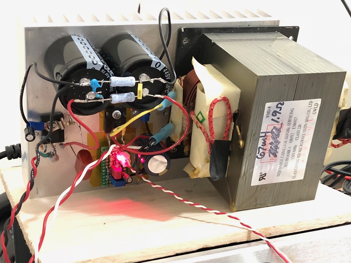
I just ordered another MOT to try out. This one is an MD-103AMR. It measures statically at 68mH and 0.56ohm DCR. It’s much heavier than the MD-803AMR that I have been using and weighs in at a whopping 10.25lbs. Hopefully that equates to more tolerance to saturation at higher currents. Will test and find out.
I have a question: If one has 4 identical MOTs and wired them in series parallel, would the overall inductance and DCR remain the same but the saturation current would increase by either 2x or 4x due to more overall stored magnetic energy? I know 40lbs of inductors is not an easy thing to put in an amp! 😀 price would be $120 or so via eBay. Or FREE if one knows how to organize through their neighborhood like our Canadian friends. 🙂
I have a question: If one has 4 identical MOTs and wired them in series parallel, would the overall inductance and DCR remain the same but the saturation current would increase by either 2x or 4x due to more overall stored magnetic energy? I know 40lbs of inductors is not an easy thing to put in an amp! 😀 price would be $120 or so via eBay. Or FREE if one knows how to organize through their neighborhood like our Canadian friends. 🙂
Attachments
Last edited:
If one has 4 identical MOTs and wired them in series parallel, would the overall inductance and DCR remain the same but the saturation current would increase by either 2x or 4x due to more overall stored magnetic energy?
I'd say the saturation current increases by 2x since the total current through the four MOTs is split in two halves, each running through two MOTs in series.
Or, in other words: the max. total energy stored in all four MOTs is 4x the max. energy stored in each single MOT. Since the magnetic energy is proportional to the current^2, the saturation current of the four MOTs is sqrt(4) = 2x the saturation current of each individual MOT.
Last edited:
X and JPS have done some excellent work squeezing 39W out of the little LU1014D device and the LuFo is on my project list but I'm wondering if anyone has considered a low power LuFo, (say similar to the MoFo, perhaps sub 20W), and how it might be realised?
You could run the LU1014D as a straight follower (no cascode) like the Mofo with a 20V supply and an inductor. Probably get about 11w out of it. Use a 24v SMPS with a MOSFET cap Mx to drop 4v and get 20V of clean slow soft start power. There will t be any speaker turn on pop with a cap Mx PSU.
On my Mofo, I just dead bugged a cap Mx right onto the same heatsink and added a CRC after it.
On my Mofo, I just dead bugged a cap Mx right onto the same heatsink and added a CRC after it.
Thanks X. Something to think on, (especially with your adaptor boards and my small stash of the LU1014D devices that is the result of the GB for Papa's donated trove) - perhaps a bi-amp solution with a LuFo for the bottom end and a Lufo-Lite for the top? Could perhaps drive both from the same preamp driver module. Will obviously have to adapt the biasing circuit if the cascode is removed.
A Lufo-Lite would be less demanding with regard to inductor selection too.
It might be interesting to compare a LuFo-Lite to a MoFo.
A Lufo-Lite would be less demanding with regard to inductor selection too.
It might be interesting to compare a LuFo-Lite to a MoFo.
Last edited:
- Home
- Amplifiers
- Pass Labs
- LuFo Amp - 39w SE Class A from 28v Rail