Hi Flancfuster,
Thanks for the balanced output version for the SuSyLu - that looks really good. 0.007% THD for 50Vpp is excellent.
Will you be making layout for PCBs? 🙂
Thanks for the balanced output version for the SuSyLu - that looks really good. 0.007% THD for 50Vpp is excellent.
Will you be making layout for PCBs? 🙂
Geeze - I take a 3-month break from amp building and you guys come up with this! I am itching to try a LuFo now. Great job, Vunce.
Hi Wtnh,
I didn’t know you were taking a break 🙂
We are working out the tweaks and fixes for a user friendly LuFo amp board. Should be ready soon.
I guess you have a new amp to look forward to. I still need to build your XFS amp that you sent me the design for. I have the BOM (for the built in SSR version even) and PCB all waiting in a box ready for a rainy day.
Went off to Florida for 3 months, leaving my workbench behind. But I am back and ready to warm up the soldering irons. 

Hi Flancfuster,
Thanks for the balanced output version for the SuSyLu - that looks really good. 0.007% THD for 50Vpp is excellent.
Will you be making layout for PCBs? 🙂
I was working on the front end to drive a source follower amplifier. Initially, I wanted to go for balanced F4 amps and my idea of design was to have the FE in a separate case and connect them with XLR cable.
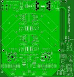
Here is the PCB layout I have in mind. The PCB was not made yet. I also put a pot to adjust 2nd order harmonic distortion (as Nelson Pass suggested for F5)
It has Voltage regulator for B+ and muting circuit with delay for output.
It can accommodate E88CC and PC88 tubes.

This is very nice work! Looks like you are ready to order boards? What is the gain of the FE? What kind of trafo were you thinking to get the required B+?
Thanks. Gain is aprox. 24dB. Requirements for transformer is:
140V @ 150mA (B+)
10V @ 3A (Heaters)
20V @ 150mA for CCS (-24V)
First, I'm waiting for your results on SuSyLu 🙂
After that I will do some modifications, if required.
140V @ 150mA (B+)
10V @ 3A (Heaters)
20V @ 150mA for CCS (-24V)
First, I'm waiting for your results on SuSyLu 🙂
After that I will do some modifications, if required.
Ok, looks good. Is there a standard transformer that has all 3 voltages for you? I am ordering a sample of a custom dual balanced coupled inductor for the SuSyLu. It may be a while before I can get the inductor. In the meantime I will build up half the SuSyLu in each monoblock chassis. Waiting to be converted to balanced output.
I didn't found a standard transformer for this requirements. Last time when I've build my balanced phono stage, using similar concept, I had to use a custom transformer. Here in Europe, Toroidy is a good supplier.
Geeze - I take a 3-month break from amp building and you guys come up with this! I am itching to try a LuFo now. Great job, Vunce.
Glad to hear your back Wtnh! I’m sure your workbench is going to get real busy soon, lots of cool projects going on

@flancfuster,
Nice tube FE board! Watching with interest 😉
Last edited:
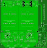
I did some small modifications to previous layout. Removed the SiC follower (not required for this application). More flexibility on size and pin distance for output capacitors.
View attachment 962839
Can you share schematic? How does mute function work? Are you using two MOSFETs as SSR’s to clamp to ground?
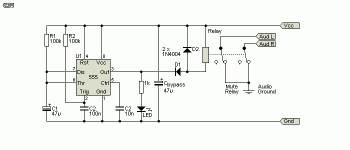
For mute circuit I'm using Rod Elliot - Relay mute circuit, with NE555 for time delay (set up for 10 sec or more), to avoid noise and high voltage on the output until heater voltage for tubes are steady. Signal stays connected to ground until relays are powered on. Easy and effective. SSR with mosfets can work nicely as well.
555 Timer

555 Timer

Last edited:
In practice, if we use separate case for tube front end, the same PCB can be used, and only positive signal will be used to drive the LuFo. If we want to put the FE in the same case (tubes can pick up noise and hum from main transformer), then I can remove the voltage regulators and use DC/DC booster. If xrk971 can share the schematic for booster, I can start making a layout. The other option is to have a separate transformer to power up the tube front end.
I prefer the FE in separate case. It gives more flexibility. One can try different power followers, SE, Balanced...
I prefer the FE in separate case. It gives more flexibility. One can try different power followers, SE, Balanced...
Last edited:
If two channels are contained on a single PCB, what are the provisions for ensuring separate Anode voltage to each channel?
I ask in the interest of getting the best stereo separation and imaging.
Edited to add:
Since this hybrid tube front end has great potential to be used with other amplifiers, some way of adjusting the gain might be very useful.
I ask in the interest of getting the best stereo separation and imaging.
Edited to add:
Since this hybrid tube front end has great potential to be used with other amplifiers, some way of adjusting the gain might be very useful.
Last edited:
.
I prefer the FE in separate case. It gives more flexibility. One can try different power followers, SE, Balanced...
I have a suitable power transformer, I can give a try: it intrigues me for a F4 or two bridged LuFo/MoFo...
If two channels are contained on a single PCB, what are the provisions for ensuring separate Anode voltage to each channel?
I ask in the interest of getting the best stereo separation and imaging.
This PCB design has only one voltage regulator for B+. Modifications can be made to have separate supply for each channel, heaters included. It will require different power transformer, with more windings, more parts and space.
Edited to add:
Since this hybrid tube front end has great potential to be used with other amplifiers, some way of adjusting the gain might be very useful.
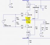
Gain can be easily adjusted via R16, R17. A dip switch can be mounted on PCB to adjust gain, but complicates the H2 adjustment.

I can share the gerbers if you are interested.I have a suitable power transformer, I can give a try: it intrigues me for a F4 or two bridged LuFo/MoFo...
Perhaps, with just one B+ regulator, there can be separate RC filtering for each channel? An intermediate solution that wouldn't require a different power transformer.
Thanks for the tip on adjusting the gain with R16 and R17. No need for a DIP switch. Only looking to decrease the gain to about 20 dB, perhaps 18 dB. The 20 dB gain setting would be for an F4 and the 18 dB setting for a VFET amp.
Thanks for the tip on adjusting the gain with R16 and R17. No need for a DIP switch. Only looking to decrease the gain to about 20 dB, perhaps 18 dB. The 20 dB gain setting would be for an F4 and the 18 dB setting for a VFET amp.
RC filtering for each channel can be implemented.
For 20dB gain, R16, R17 must be increased to around 850 ohms
For 20dB gain, R16, R17 must be increased to around 850 ohms
- Home
- Amplifiers
- Pass Labs
- LuFo Amp - 39w SE Class A from 28v Rail
