I don't recall the Fairchild mosfets being particularly expensive back in the day. For example, when I bought my stash of FQA19N20C and FQA12P20 (the original parts used in the F5) they were in full production and were price-competitive with IRFP240/IRFP9240.
ZM has got better results because he uses a slightly different amp and also a higher bias.
I was comparing my results with my results, so the improvement was over what I had and what I have.
What I wanted to show is that in my amp(which is only the ops of ZM’s plethora of pinjatas with the cascoded lu instead of the nch mosfet and a different front end with no gnfb) I got lower thd by lowering the vds of the lu.
I asked here about the vds because it was a more appropriate thread.
Sorry I didn`t mention this until now.
Another thing to mention is that the loads even if both 4 ohm one can be more inductive than the other and you get slightly different results.
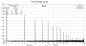
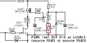
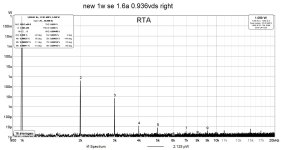
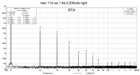
So in the end I lowered the value of one resistor (R135 in this schematic https://www.diyaudio.com/community/attachments/ludef-schmtc-png.937325/ ) from 4.7k to 2.5k and lowered more the vds.
Doing some tests I decided that the best compromise is at 0.72vds. At 11w if going under this value the second harmonic starts to fall under the third and going lower the overall thd increases .
By changing that resistor it changed also the phase of the second harmonic. Now(with 2.5k) if I set back 2.5vds for the lu I get positive phase instead of negative.
Both channels have same results at same vds.
I was comparing my results with my results, so the improvement was over what I had and what I have.
What I wanted to show is that in my amp(which is only the ops of ZM’s plethora of pinjatas with the cascoded lu instead of the nch mosfet and a different front end with no gnfb) I got lower thd by lowering the vds of the lu.
I asked here about the vds because it was a more appropriate thread.
Sorry I didn`t mention this until now.
Another thing to mention is that the loads even if both 4 ohm one can be more inductive than the other and you get slightly different results.
So in the end I lowered the value of one resistor (R135 in this schematic https://www.diyaudio.com/community/attachments/ludef-schmtc-png.937325/ ) from 4.7k to 2.5k and lowered more the vds.
Doing some tests I decided that the best compromise is at 0.72vds. At 11w if going under this value the second harmonic starts to fall under the third and going lower the overall thd increases .
By changing that resistor it changed also the phase of the second harmonic. Now(with 2.5k) if I set back 2.5vds for the lu I get positive phase instead of negative.
Both channels have same results at same vds.
Attachments
it is always good to try whatever you can think of trying, then in the end choosing best set of compromises
what that is going to be (best set of compromises) depends only of you
just don't be obsessive about just one factor - in this case absolute THD figures
in short - determine what your main goal is - absolute THD numbers, or maintaining THD Spectra through entire power range, or phase of dominant ......
for me - THD Spectra, then maintaining it through entire power range is more important than absolute THD figures
What I am trying to do is to see is if I like thd and which type of it I like most.
Until now I noticed that I do like the impact of the negative second on the low end. I feel less this effect with the positive second dominant and even less with the third dominant.
Today I wanted to see how much the effect attenuated if I lowered the negative second but unfortunately the negative went positive by halving the resistor value.
I have to see how to make it negative again and get 0.72vds on the lu, probably need to decrease less the resistor value or use a smaller zener instead of the 7v one.
One thing that I don’t understand is how could the smaller resistor change the phase if it’s ac bypassed?
Lu is changing that, not governing voltage you're varying
I mean, you're changing transfer characteristic of cascoded Lu as system/part
I mean, you're changing transfer characteristic of cascoded Lu as system/part
something is fishy
if we assume rail value of 22V5, with values I devised, there is (22V5-7V5)/3K3=4.54mA through R134
then we have 7V5/(2K+4K7)=1.19mA through resistors, so 3.4mA goes through zener, good enough for stable zenering
if you change 4K7 to 2K5, current through resistors goes to 7V5/(2K+2K5)=1.66mA, decreasing current though zener to 2.87mA
so, either your zener is current starved, and you also have Gremlins in dark corners, or ..........
decrease R134 to 2K2, if you want to decrease value of R135
Well yes, initially I removed the 2.5k resistor and soldered back the 4.7k with 100k. Like this I can reach 0.5vds on the lu.something is fishy
Still positive phase.
Looking better I seen that I had a reversed connection on the input of the soundcard. So all good now I get negative phase.
What I noticed is that the low end extension I was mentioning is created by the level of h2. More h2 you have the bigger is the smile on your face, well until a certain level of h2.
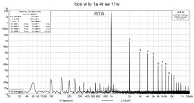
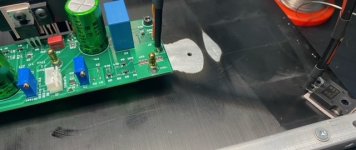
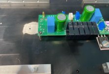
Having dual mono bridged amps I will remove one amp from each enclosure and move the pch mos to the free heatsink(connecting it with some wires) so I can go from 1a bias to 1.6a
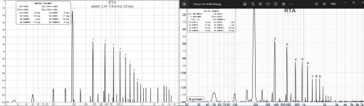
main goal was to have an amplifier more efficient and with lower thd than the aleph j that I had first. The aleph was biased at 3.2a, the actual ludef with current mirrors is biased at 1.6a. My speakers are 3.4ohmin short - determine what your main goal is - absolute THD numbers, or maintaining THD Spectra through entire power range, or phase of dominant ......
Seems that I accomplished the goal very nice, half the thd at half the power dissipated and also no global feedback.
I settled for ~0.95Vds for the lu and 1.6a bias, I didn`t go for the lowest thd but set for ~10x negative second over the third at 1W and ~3x negative second over the third at 11W
Attachments
Finally after a year of slow progress / procrastination my LuDEF is ready for power on...
Can anyone direct me to the post # with the initial start up sequence?
I've assumed that I remove the front end jumper and get the LU /backend biased first, then move to the front and connect the jumper when done.
The bias' are on the circuit diagram, but I'm not seeing the expected numbers.. No magic smoke as yet.
Thanks
First power-up and biasing procedure is the same as for the SissySIT:
https://www.diyaudio.com/community/threads/sissysit-r-3.371272/
Aim for 1.5 A idle current and always remember that any bias change takes about minute or two to settle. So, after powering amplifier there will be no current through output transistors before one minute passes and from that point, it will slowly ramp up.

Has anyone found any benefit from tuning the LU bias/ voltage? I've got 2v4, as per the circuit diagram.
165mV bias on the FETs and 20mV on the front end. Offset is zero.
I don't have a distortion analyser, so I guess that I'll have to tune the LU distortion by ear...if there are any gains to be had.
Thanks for all the help 🙂
165mV bias on the FETs and 20mV on the front end. Offset is zero.
I don't have a distortion analyser, so I guess that I'll have to tune the LU distortion by ear...if there are any gains to be had.
Thanks for all the help 🙂
Very early days, amp has been playing for 3 hours now and I'm not really hearing the Lu. I've had an M2 in my system a couple of times and this sounds very similar, at least to my ears at the moment.
Shall I try a lower Vds on the Lu? Maybe 2v?
I think I'd like more 2nd order
Shall I try a lower Vds on the Lu? Maybe 2v?
I think I'd like more 2nd order

even with benign load, there is a difference in THD vs. regular M2 iterations
with tougher loads, there is a world of difference
all due to Square Law OS arrangement
with tougher loads, there is a world of difference
all due to Square Law OS arrangement
Really late to this party but wonder if ZM still ha any circuit boards available as none as far as I can see at Store. Tried a couple of emails with no answer. Found I had a stack of LuDEF from the Zen 9 from yeats ago and no ppint wasting them.
- Home
- Amplifiers
- Pass Labs
- LuDEF