

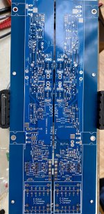

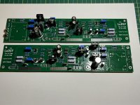
Hey, Zen Mod, the little critters you sent me are already on the boards! Not the cleanest work in the world, I know. But I am OK with myself about that so far. We'll see if I can be proud of myself when the bias setting time will come... 😉
And the PSU is waiting for the boards already. So now - the fun part - boards stuffing 🙂
I don't know exactly why, but I went with 2x19V secondaries this time (instead of usual 2x18V). Perhaps because this LuDEF has to be special 🙂 It gives 26.2V unloaded now. Hope this is to the better, not the worse...
Thanks a lot!
Alvydas
Attachments
I went with 2x19V secondaries this time (instead of usual 2x18V). ....... Hope this is to the better, not the worse...
Damn the torpedoes! (Tom Petty)
Full speed ahead!
I have 25 V loaded. 🙂
Whatever you say about it - nobody in the world has that looking LuDEF 😀
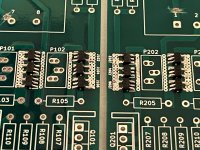
No bypass caps, autoformers and output devices on the boards yet, but it's time to check on the setup process.
ZM, can you help me with that once more to be sure about the details.
My plan is:
1. With the state of the boards like they are now (no autoformers, no output devices and no bypass capacitors), I connect V+, V- and GND from the PSU to each channel and check if I can get 20mV on R106 with the help of P101. What about P102 - what is the purpose of it?
2. If I have 20mV on R106, I solder in autoformers bypass capacitors (still waiting for them), output devices and mount the boards on the heatsinks.
3. I set 2V4 on D-S of LU1014 adjusting P105.
4. I set Iq 1A5 (165mV accross R129) adjusting P104
5. I set DC close to zero adjusting P103
6. Reapeat steps 3 to 5 to get everything in balance.
7. Listening to some fine music.
Does that sound like a proper plan?
Thanks
Alvydas
Attachments
procedure more or less same as written ( see first post in proper thread) for SissySIT R.3
if you set buffer trimers as explained (lower one setting Iq to 20mA, upper one setting DC offset of buffer), you'll leave buffer setting for later, dealing first with OS setting
trimpot at CCS chip is for Iq setting ( preliminary set to 0 ohms!!!!) and other one is for amp Output DC offset
difference to SissySIT procedure is that somewhere after semi-set Iq, you need to tweak Uds of LU to prescribed
it is iterative process - setting Iq and LU Uds ...... takke care that final setting of that is done in temp equilibrium
not so important for Iq and DC Ofsett - but important for LU Uds
so- up to SIssySIT R.3 thread - read that..... think
Thank you, Zen Mod. Read it twice, thought about it, set trimpots as recommended.
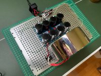
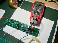
As I do not have a jumper to disconnect the autoformer from the input, I decided to connect my PCBs to the power supply now and try to set up the input stage. All went smoothly!! Had no problems to set Iq to 20mA and zeroed the input stage DC without any troubles. And the smoke still stayed inside! So, looks that my iron SMD soldering skills were good enough to stick the little jfets to the boards 🙂
I suppose I am safe now to solder Edcors to the boards and brace myself for the next challenge - solder the LU1014 to their adapter boards. I will have to literally fry them on the pan 🙂 Greenhorn way of cooking... 😀 Wish me luck 🙂
Attachments
I didn't got that you don't have OS parts fitted
Of course that is possible and doable setting input buffer that way
in fact, any small PSU is adequate for that operation , even +/-12V will do the job - enough juice for JFets
Of course that is possible and doable setting input buffer that way
in fact, any small PSU is adequate for that operation , even +/-12V will do the job - enough juice for JFets
By the way, I found using the short probes essential. Using the long (about 1 m long) ones gives me 25.5mV on the same trimpot setting.
Gents, I'm quite late to the party, but I think I would really like to build one of these. Can someone please point me to the post with the BOM and send me an invoice for a pair of boards.
Which transistors do I need to have matched? All of them?
Looks like each board needs the following:
6off Front end JFETS, BD139/140, BC546, JRF510, IRFP9140, IRFP240 and a single LU1014(D). That's not messing about!
All help very greatly appreciated
Dan
Which transistors do I need to have matched? All of them?
Looks like each board needs the following:
6off Front end JFETS, BD139/140, BC546, JRF510, IRFP9140, IRFP240 and a single LU1014(D). That's not messing about!
All help very greatly appreciated
Dan
Hi Dan,Gents, I'm quite late to the party, but I think I would really like to build one of these. Can someone please point me to the post with the BOM and send me an invoice for a pair of boards.
Which transistors do I need to have matched? All of them?
Looks like each board needs the following:
6off Front end JFETS, BD139/140, BC546, JRF510, IRFP9140, IRFP240 and a single LU1014(D). That's not messing about!
All help very greatly appreciated
Dan
I think you will find everything here https://www.diyaudio.com/community/threads/ludef-kit-packages.372981/
Contact Mighty ZM.

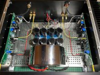
After a long and adventurous journey, my LuDEF is playing a "swanderful" heart-sweetening music today!
I know this one will be my favourite and dearest amp of all the 6 Papa/ZM creations that I've built and own (ACA, M2X, F5, Aleph J Zen, Aleph J and LuDEF). This amp is special to me in so many ways. That was my first ever attempt to learn KiCad, make my own PCB layout and order PCBs from a fabricator. I did make mistakes (some very stupid), had to find them and use some "bandage" under the PCB in the process, but that's the best way for every greenhorn to learn something, isn't it?
Another thing that makes this amp so special is the number of people and the great generosity of them that made all this possible!
My sincere thanks to Nelson Pass himself for donating the LU1014D from his stash, @woofertester for matching them, @JPS64 for designing the adapter board, @wg45 for organizing the group buy of the adapters and distributing the Papa's LU104D, Zen Mod for generously sending me all the matched input JFets and, of course, for the design of the LuDEF schematics and all the other things in the word he does for us, including all the good mood he brings here!
It's such a good feeling to contemplate about all these people and the challenges that I went through myself to build this one.
Let it be music!
Attachments

ZM, finally got my 2SK2145BL from Mouser, built the tester with the adapter that has been collecting dust since the middle of December and measured all 50 of the little buggers (twice). I was getting a lot of out of spec high currents and decided that my measuring DMM (Fluke!#?!) was not up to there challenge. I intserted a 1R resister and got much better numbers measuring mV. In the end the majority of the batch was all very close together between 11 and 14 mA. I have 18 that are over 14 and under 16 with one over 21 mA. Does this match your experience? (Except for maybe the questionable measuring accuracy)it depends of matching purpose
say - for triplets I'm using in buffers - I'm content with having all 3 in 0.5mA ........that difference being further diminished when JFets are actually biased in circuit to significantly lower Iq than their Idss is
for 2+2 I'm using in LTP - I'm keeping them in same bracket (0.5mA), but then I'm combining them to have closest sum of twos
rough example :
10mA, 11mA, 12mA, 13mA
then 10mA and 13mA are used for one LTP side, 11mA and 12mA used for other side of LTP
trick stolen from Pa
if I tell you from which exact circ, I would need to shoot you

yeah, there are enough of them going above BL range, but no biggie
say that I still didn't saw any above 26mA (sum), which is just a tad above 12mA per unit
remember that they're declared BL per unit, so max sum 2x 12mA, as per book
say that I still didn't saw any above 26mA (sum), which is just a tad above 12mA per unit
remember that they're declared BL per unit, so max sum 2x 12mA, as per book
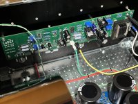
My LuDEF is doing fine and I am enjoing it all the day long. But I have a few questions concerning the temperatures.
Mosfets are running at about 60C and LUs at 50C, heatsinks (standard greenhorn 4U300) at about 55. All good, in my understanding.
Q103 and M101 are at about 60-65C - looks a bit on a hot side, but is it OK, or my heatsinks are a bit too small for them?
Q101 and Q102 are cooler, below 50.
What I am mostly concerned of is the power transformer. It's the first time I got the potted Supremer Audio grade from Toroidy. It's 400VA, and it runs quite hot, about 65C (above the Papa's X*?@! scale) and I cannot keep hands on it. Is it OK? I don't think my mounting has created unwanted winding around it (should not even be possible with the potted Toroidy x-former). As it is hotter than the environment, so it should be heating from inside.
I have never noticed the transformer heating with the usual Audio Grade from Toroidy in my other amps.
And a note about the output offsett. Noticed it is quite sensitive to the temperature as well. Merely taking off the top cover of the amp very quicky makes the offset to go from 0mV to about -50mV. And when you put the cover back, it gradually comes to zero again in about a minute or so. It's ok, just interesting.
Would be thankful for the comments.
--Alvis
small buggers - use bigger sionks if you are not happy with temperature
offset - not biggie
I believe with my pcbs it's more stable, but who cares about 50mV
Donut - 65C is showing how Supreme it is, with measly 160VA of load
offset - not biggie
I believe with my pcbs it's more stable, but who cares about 50mV
Donut - 65C is showing how Supreme it is, with measly 160VA of load
- Home
- Amplifiers
- Pass Labs
- LuDEF