Hi ZM,
you're onto something... it's 0V on the R115 (the 68 ohms) and 0.65V on R114 (the 22 ohms).
What going on? 🙂
you're onto something... it's 0V on the R115 (the 68 ohms) and 0.65V on R114 (the 22 ohms).
What going on? 🙂
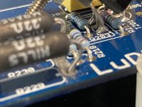
check orientation and proper value of all zeners
check soldering
check resistors
btw. "on" is slightly unclear term - always use "across" which exactly means voltage sag across that one resistor
"on" can be used in context of having black probe on some reference ( either GND or output or whatever agreed) and red probe pocking to one end of said resistor
now - 0V65 across R114 means lower CCS is doing it's job , sourcing 0V65/22R=30mA, but question is where that current goes , because it is intended that it goes through R115 (so seeing 30mA*68R=2V across the same)
check for shorts - either your soldering or (highly improbable) short in pcb traces
Thanks alot ZM!
Noted! The voltage is _across_ the resistor. Sorry for the incorrect use of the terms.
Will do all the above suggestions tonight. As to the shorts, after this weekend of electronic crazyness, like a crimped terminal not conducting and driving me crazy for a couple of hours, I can't rule anything out. 😉

ZM ok a small update from visual inspection and I was measuring resistance in various places and found something strange. On the board in service I am measuring across D and S of the irf510 and find as if I am charging a capacitor the resistance starts small then increases to ~400ohm after that it goes open. On the other board I am always measuring an open circuit between D-S. I am thinking this could be because on the second board the output mosfets are not soldered and the board is not wired so it may behave differently. Still it is a difference. Is this normal behavior? I will remove the board again and check more details. I don't want to unsolder the mosfet unless absolutely necessary and I have no more 510s and I have to order more.
do you have any N channel IRF?
510,520,530,610,620,630 - any of them will do the job, at least for test - you can change it later to 510
if all zeners are oriented properly and proper values positioned where need to be, and there are no shorts between traces ....... then mosfet is main candidate
circuit is too complicated to make any prediction how it could behave under ohmic measurements in all positions on pcb ....... if you have two fully assembled pcbs you can compare, but you don't
The zener orientation is right, and since I installed all resistors right I would say the zeners value are correct too but I would have to check.
is it possible to test zeners w/o taking them out?
There are no shorts anywhere
I did replace the 510 with my last 610 and the offset went to 0.2V briefly but jumped back up to 1.2V after a power cycle. So it looks like the 610 also blew up. What would cause that to happen?
I unfortunately forgot to check the r115 voltage drop when it was kind of working.
Amend: zd102,103 and 106 are correct, I measured the drop. The others is not clear but by elimination I would say they are installed right.
Last edited:
no way to test zeners for voltage in circuit
that's the reason why I'm always putting them in pcb with voltages marks visible, so later when I'm hysteric I can check, using strong damn Loupe
don't have an idea what can cause IRF going south ...... I mean , 7V5 is important value for setting LU cascode voltage, other 2 zeners practically can be anything between prescribed 5V6 and 15V ......... and 5V6 chosen not just as gate protectors but also as modulation swing limiters, in case someone barge with zillion input volts in amp
something must be amiss
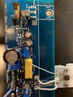
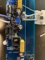
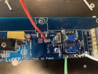
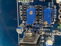
care to post some pics?
that way I'm at least going to feel less in the dark
that's the reason why I'm always putting them in pcb with voltages marks visible, so later when I'm hysteric I can check, using strong damn Loupe
don't have an idea what can cause IRF going south ...... I mean , 7V5 is important value for setting LU cascode voltage, other 2 zeners practically can be anything between prescribed 5V6 and 15V ......... and 5V6 chosen not just as gate protectors but also as modulation swing limiters, in case someone barge with zillion input volts in amp
something must be amiss
care to post some pics?
that way I'm at least going to feel less in the dark
Yeah, no then all the zener are correct. I measure the voltage across the 7.7 and 8.2 V ones and nothing would be adjustable if this were wrong.
I will post the pics tonite. Thanks so much!
I will post the pics tonite. Thanks so much!
only 7V5 is having full voltage across, in functional circuit, serving as reference/regulator
other ones doesn't have anything near max voltage across them, in functional amp, serving as protection and limiting devices
in proper amp voltages across zeners are:
ZD105 - aroundish 4V, which is mosfet Ugs
ZD104, aroundish 1V5, which is LU Ugs
ZD101, aroundish 4V (which is IRF Ugs) decreased by LU Ugs, so say 2V5
of course, ZD102 and ZD103 are having different role, level shifters for LT3092 (result LT3092 seeing lesser voltage than sum of rails), each having 8V2 across
Yes I did measure the ZD102,103 and 106 and they seem to have the rated drop so these are correct.
I think I get something around 4V for one of the other remaining, I forget which one, but it points to it being the zd105.
I am pretty sure I see no voltage drop across on one of the zeners.
Will remeasure again tonight with your numbers in mind and put pictures.
I think I get something around 4V for one of the other remaining, I forget which one, but it points to it being the zd105.
I am pretty sure I see no voltage drop across on one of the zeners.
Will remeasure again tonight with your numbers in mind and put pictures.


well, ook, I can't see anything wrong
I know that I made all sorts of ookups, mostly because of ....... well, because I'm Mighty ZM, Master of Omniookups
I did assemble one channel of Babelfish M25 with 2 Nchannel mosfets (instead of compl. pair)
I did assemble one channel of Babelfish M25 with swapped mosfet places......
so, bought damn clicklick white marker pen, so each mosfet being marked N/P on top edge, prior to mounting
I can't see nothing on your pictures; probably best is to cool down for few days, then get it, take printed schm sheet and stare at it and on pcb
use this printed too
Attachments
Hi ZM
I m gonna work on the mechanical for the other side, put it all together see if the behavior is different. This one got me confused.
I m gonna work on the mechanical for the other side, put it all together see if the behavior is different. This one got me confused.
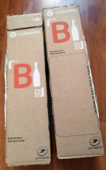
Ha! Look what I got ..............
.......from L état de liberté, égalité et fraternité ....... more precisely - from Sud de France
our own Toto34 decided to rejoice Mighty ZM, so he sent two of his own production
(note that I have appropriate tool for unpacking those)
Merci beaucoup Toto34 ....... I'm going to have few glasses these days, thinking well of all Greedy Boyz
🙂
Attachments


Just don’t evaluate amplifier designs while enjoying that. Any design will sound as "best ever made". 😀

- Home
- Amplifiers
- Pass Labs
- LuDEF