I've completed a LuDEF!
The pot adjustments for offset and bias all
went as expected with correct values set.
But audio output is extremely low on both channels -
can just barely hear it.
I've checked all the values and part locations.
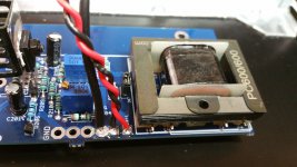
I'm using an Edcor 600/600.
Is this the right one?
I noticed Sissy and M2 use the Edcor 600/15K.
-Bruce
you didn't forgot jumpers , JP101 and JP201?

check continuity between JP pin marked X and R111
write down resistance
check resistance/continuity between JP pin marked X and GND
you didn't forgot jumpers , JP101 and JP201?
check continuity between JP pin marked X and R111
write down resistance
check resistance/continuity between JP pin marked X and GND
Yessir!! JPX01 jumpers were on!
Resistance between JP pin marked X and R111 - 105 ohms
Resistance/continuity between JP pin marked X and GND - 38 ohms
Attachments
Last edited:
lemme think
need some food then some coffee, then can think
didn't tried those pcbs with Edcors, but did zillion checkups and everything was logical, last time this morning
both channels same behavior?
source can't be blamed/is checked?
need some food then some coffee, then can think
didn't tried those pcbs with Edcors, but did zillion checkups and everything was logical, last time this morning
both channels same behavior?
source can't be blamed/is checked?
...need some food then some coffee, then can think...
Now you're sounding mortal! 🙂
Yessir!! JPX01 jumpers were on!
Resistance between JP pin marked X and R111 - 105 ohms
Resistance/continuity between JP pin marked X and GND - 38 ohms
your measurement is confirming that autoformers are connected and in continuity
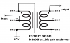
just checked - everything is by the book, Edcor PC 600:600 pinout just snatched from their site
see enclosed
do you have scope, or if not scope , at least some handy signal gene, able to give under 1V of anything between 400Hz and 1KHz - that you can measure directly with DMM set at Vac
if something is about autoformer, it can be only wrong phasing mark on Edcor site
Attachments
Thanks for the quick reply oh mighty Zenmod!
Yes, both channels have the same problem.
Yes, have signal gen and scope.
Where is a good place to look?
Bruce
Yes, both channels have the same problem.
Yes, have signal gen and scope.
Where is a good place to look?
Bruce
Last edited:
put , say, 100mV of signal in input of amp
no speaker or load needed
then see what you get on B pin of opened JPx01 jumper
then close jumper and see what you're getting at Rx11
it could be 100mV in, same on B pin, close to 400mV at Rx11
no speaker or load needed
then see what you get on B pin of opened JPx01 jumper
then close jumper and see what you're getting at Rx11
it could be 100mV in, same on B pin, close to 400mV at Rx11
I've just checked against gerbers of Pa's M2
PC 600:15K is having same pinout as 600:600, and everything complies between his gerbers and what I did here
now I'm puzzled
check all resistor values, check everything
post pics
PC 600:15K is having same pinout as 600:600, and everything complies between his gerbers and what I did here
now I'm puzzled
check all resistor values, check everything
post pics
I put 300mv of 1khz signal in.
At the B pin of the open jumper I get 300mv.
I closed the jumper and at Rx11 on both channels I get nothing.
On the Edcor I get these readings:
Pin 1 - 584mv
Pin 2 - 300mv
Pin 3 - 0v
Pin 5 - 0v
Pin 6 - 300mv
Pin 7 - 584mv
I will begin double checking everything and take pics.
I have a Cinemag on order - don't know when it will come though.
-Bruce
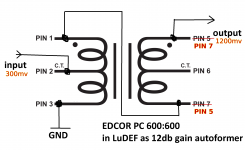
I did an experiment with a spare Edcor 600/600 transformer on the bench.
It looks like its primary/secondary are reversed from expected.
Configured as it is used on the LuDEF pcb with pins 1 and 7 connected I
put in a 300mv 1khz signal on pin 2 and got nothing on the output (5)
Configured with 5 and 7 reversed I got 1200mv from the output pin (7)
It looks like its primary/secondary are reversed from expected.
Configured as it is used on the LuDEF pcb with pins 1 and 7 connected I
put in a 300mv 1khz signal on pin 2 and got nothing on the output (5)
Configured with 5 and 7 reversed I got 1200mv from the output pin (7)
Attachments
well, they suck!!
improvize, xacto knife and tiny wire on pcb
or wait for cmgz
they really suck.... I have 6 or 7 pairs of 600:15k in wshop, but none 600:600, so I just trusted them for their own pinout
improvize, xacto knife and tiny wire on pcb
or wait for cmgz
they really suck.... I have 6 or 7 pairs of 600:15k in wshop, but none 600:600, so I just trusted them for their own pinout
being on the road to Mountain today,then had to nap
that's why late posting
and now little boss needs my laptop, left her at home
I hate web, typing on phone
that's why late posting
and now little boss needs my laptop, left her at home
I hate web, typing on phone
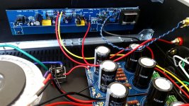
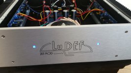
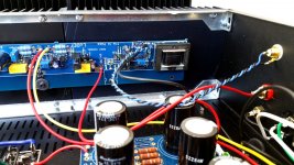
Many Thanks for the troubleshooting help Oh Mighty Zenmod!
I reworked the offending Edcor parts and reinstalled them - didn't want to cut up a fine PCB!
I did a quick power measurement and LuDEF
goes right up to around 25 watts into 8 ohms at clipping - very nice!
And now they are playing beautiful music!
Very fine, detailed - magnificent!
Some photos of my build:
-Bruce
Attachments

Great detective work banderson546! Now just twist those power wires and you'll get an official 'fugly'! 
But as this seems to be the first LuDef in existence outside of the OPLDF, you deserve an award.
Fugly! (means awesome job in ZMEngrish)
But as this seems to be the first LuDef in existence outside of the OPLDF, you deserve an award.
Fugly! (means awesome job in ZMEngrish)
Last edited:

I reworked the offending Edcor parts and reinstalled them - didn't want to cut up a fine PCB!
Bruce, can you please explain how you reworked the Edcors that you did not have to cut vías on the PCB?
Thanks
-Alvis
Many Thanks for the troubleshooting help Oh Mighty Zenmod!
I reworked the offending Edcor parts and reinstalled them - didn't want to cut up a fine PCB!
I did a quick power measurement and LuDEF
goes right up to around 25 watts into 8 ohms at clipping - very nice!
And now they are playing beautiful music!
Very fine, detailed - magnificent!
Some photos of my build:
-Bruce
Fugly!
and inventive - including how you decided to take your own care of LU mounting
........
And now they are playing beautiful music!
Very fine, detailed - magnificent!
.....
that - you can't expect less, with nice autoformer gain, combined with Berserked OS
Bruce, can you please explain how you reworked the Edcors that you did not have to cut vías on the PCB?
Thanks
-Alvis
The rework I did reversing pins 7 and 5 on the PC600/600's
was not as clean as I would have liked - I'd call it crude but effective.
I snipped off the thin magnet wire on pins 5 and 7. Scraped off
some coating on the end of each wire with an exacto knife.
Then soldered extension wires to extend each pin over to the correct pin.
I covered the wire extensions with a small piece of insulation.
I could have done cuts and jumps on the PCB but I was trying
to keep it original so I wouldn't have to undo things
if sometime I wanted to install Cinemags.
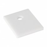
I used Aluminum Oxide Ceramic Thermal Pads from Digikey (4180G-ND) for IRFP240's,
IRFP9140's and the LU1014's.
For the LU1014's I put two pads under each one with each part facing up.
On the Right Channel PCB, extension wires from the two outer pins of the LU1014 part
to the PCB had to be reversed.
It really is a great sounding AMP!
Thanks ZenMod!
But now I'll have to collect the whole set!
Have to look into an Iron Pumpkin and an Old Soul!
Attachments
- Home
- Amplifiers
- Pass Labs
- LuDEF