no, besides some wakoo effects Lu is getting in DEF arrangement - there is some Ugs action happening
adapter pcb is big enough, but screw position too far from center
making it wider (if shorter) and allowing for 2 side positioned screws?
Good idea - we can add side mounted screw holes.
@ lhquam and Marconi:
The LU1014D is SMT soldered onto the copper PCB pad using traditional SMT paste method and hot plate or oven or hot plate plus hot air.
Insulated Metal Substrate (IMS) works by having a copper trace or pad deposited on an insulation layer between metal substrate. Usually epoxy of some sort is my guess. The metal substrate is then attached to the heatsink beneath. The part is bonded the the copper by reflow solder with traditional SMT methods.
Last edited:
Hi Folks,
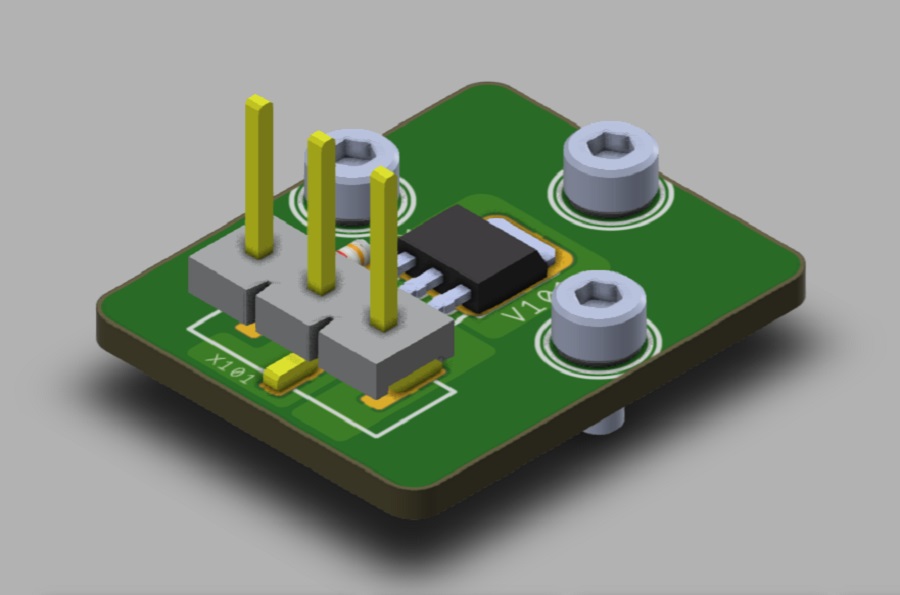
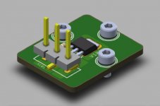
As promised, here are the complete manufacturing data for the LU1014D TO247 adapter for IMS PCB construction, now incorporating ZM's suggestion of side mounted screw holes in additon to the original top mounted one. I will order a few to make a verification unit to test to make sure it works. Once proven to work, these will be availabe as an optional part of the GB for the LU1014D's that wg45 is organizing in in the GB forum. Of course, anyone is free to manufacture these for themselves with the data here for non-commercial DIY use.
A big thanks to JPS64 for a beautiful and useful design!
Have fun!
Attachments
That is exactly what my cure tracer produces. You also have the wonkiness after 5V that I observed.
Here's an extract from Pass Zen v8:
In the case of JFET part LU1014, we note that with a gate voltage of –1 volt, the curve is concave below about 5 amps and 4 volts.
In this range it has that triode character, and this is the area of interest to us here.
I did another trace for twenty LU1014D, all with Vgs at -1v
Attachments
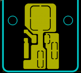
PCB is made of aluminum covered with an electrically insulating epoxy dielectric. Thermal conductivity is 2W/(m K) according to manufacturing house website specs.
That adapter board looks good. It will be interesting to see the resulting temperature difference between the drain lead and the heatsink for a few wattage values.
XRK971:
Are the thermal pad connections really needed? If so, do you have an estimate of the current capacity of those connections?
Are the thermal pad connections really needed? If so, do you have an estimate of the current capacity of those connections?
You mean the thermal relief spiders? Probably doesn’t matter on an aluminum substrate. JPS64 will have to answer what the current capacity of the thermal relief spiders. I’m sure it’s quite high but we probably don’t need them.
lately there was no shorter answer, leading to bigger document
what's wrong with regular praxis, layman terms?
I've seen termals in all possible inappropriate positions ...... so lhquam's question is more than legitimate
if I can choose, I'm always choosing hefty iron, high temperature and fast blast, rather than pad made for Sissies
what's wrong with regular praxis, layman terms?
I've seen termals in all possible inappropriate positions ...... so lhquam's question is more than legitimate
if I can choose, I'm always choosing hefty iron, high temperature and fast blast, rather than pad made for Sissies
Last edited:
I think we can get the thermal reliefs removed and post the updated files. For hot plate soldering of an IMS board, thermal reliefs really are not needed.
hot plate or not, soldering being different issue (per se) , but these thermals are bottleneck, current-wise
name of the game is, at least what lhquam's interests are, to explore use of LU in borderline conditions, current and dissipation-wise ...... and proper interface pcb must allow that, or there is no purpose, except to look nice
name of the game is, at least what lhquam's interests are, to explore use of LU in borderline conditions, current and dissipation-wise ...... and proper interface pcb must allow that, or there is no purpose, except to look nice
Is the metal tab of the LU1014D connected to the drain, possibly providing the best means to make the electrical connection?
The best connection to the drain is the tab. The source pin is the most current limited connection. The internal bond wires, which we can do nothing about, are also limiting.
I cannot find an image of the LU1014D mounting technique for the FirstWatt F3. Did Nelson use some kind of spring clip to hold the package down against the heatsink, relying on goop and the anodizing (aluminum oxide) as the insulator.
The equations of IPC-2221 have been implemented as an online trace width calculator by Digikey and is very handy. I measured the thermal relief dimensions of 0.6mm wide x 0.3mm long and assuming 1oz copper and a 20C permissible temperature rise, each relief can sustain 1.1A of current. The worst case is the one with three reliefs and that would be able to do 3.3A. The dissipation across each releif is about 300uW and each has about 300uV votlage drop across the relief. So it is indeed a bottleneck and we will remove it. Thanks for pointing it out.
Cheers,
X
PCB Trace Width Conversion Calculator | DigiKey
Cheers,
X
PCB Trace Width Conversion Calculator | DigiKey
I cannot find an image of the LU1014D mounting technique for the FirstWatt F3. Did Nelson use some kind of spring clip to hold the package down against the heatsink, relying on goop and the anodizing (aluminum oxide) as the insulator.
I held the tab to the sink with a large flat washer (at an angle) and
counted on the silicone and anodizing to withstand the couple volts...

Arrrrrr...
- Home
- Amplifiers
- Pass Labs
- LuDEF