What do you mean by that (or why and how to be precise), Kean? The chart limits are manually edited so to compare both amps. But I believe you are referring more to the second one?
Open the simulation command window where you specify the simulation time. You should set "time to start saving data" to some number of cycles of your test frequency. Or you can edit the "time range" options in the FFT diologue, but using the simulation command will save time. The abruptly starting sine wave input can cause a starting impulse and drift which will obscure the noise floor.
Next, in the FFT dialogue, go to "windowing" and select either Hann or Blackman. You will need to re-select it after you close LTSpice, but the default window is not appropriate for audio.
Very nice thread I have been following it.
It has helped me a great deal in learning my way around LTspice.
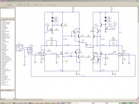
Mooly,I like the Hexfet shcematic that you have posted I have been working with A very similar design using circuit maker for a while.
Only it uses to 2N3055's for outputs and a TL082 opamp for the input stage rather than bjt's.
I just got it working in LTspice last weekend to verify my results from circuitmaker.
I have been able to scale the design all of the way down to 2 ohms and close to 1 ohms on +/- 18 v supplies and +/- 22v using a NE5534 opamp (and higher voltages with some power supply tricks) with incredible simulation results.
As well as a BTL configuration.
But that is were things start to get a little challenging and really needs to be built inorder to work out the issues.
Also I had changed the bjt ccs to an fet as well otherwise it would have been the same
I like it much so that I think that I have to build this amp just to find out for myself of its quality.
It seems that my THD's are around .005% to .002% and better in a class a mode.
The lowest I got was around .0008% THD or so !
Here is my version for you to try and I also have used a TIP32 model from onsemi as well with just a few tweaks in place of Q5's D45H11 as I had just learned how to add Model's.
I would be interested in hearing what others think as well.
Any way thanks for this very informative thread as I will keep on reading and following it closely.
Thanks !!
jer 🙂
P.S. The one question I have is how do you get LTspice to display the THD in the log file like the examples that you have shown?
It has helped me a great deal in learning my way around LTspice.
Mooly,I like the Hexfet shcematic that you have posted I have been working with A very similar design using circuit maker for a while.
Only it uses to 2N3055's for outputs and a TL082 opamp for the input stage rather than bjt's.
I just got it working in LTspice last weekend to verify my results from circuitmaker.
I have been able to scale the design all of the way down to 2 ohms and close to 1 ohms on +/- 18 v supplies and +/- 22v using a NE5534 opamp (and higher voltages with some power supply tricks) with incredible simulation results.
As well as a BTL configuration.
But that is were things start to get a little challenging and really needs to be built inorder to work out the issues.
Also I had changed the bjt ccs to an fet as well otherwise it would have been the same
I like it much so that I think that I have to build this amp just to find out for myself of its quality.
It seems that my THD's are around .005% to .002% and better in a class a mode.
The lowest I got was around .0008% THD or so !
Here is my version for you to try and I also have used a TIP32 model from onsemi as well with just a few tweaks in place of Q5's D45H11 as I had just learned how to add Model's.
I would be interested in hearing what others think as well.
Any way thanks for this very informative thread as I will keep on reading and following it closely.
Thanks !!
jer 🙂
P.S. The one question I have is how do you get LTspice to display the THD in the log file like the examples that you have shown?
Attachments
Last edited:
Just remember it can give falsely awful results. Always double-check with the FFT. Here is an example command you can plug in immediately:
.four 1KHz V(Vout)
For more info look it up in the LTSpice manual which is easily available via Google search.
Mooly, remember my set of commands in that Ampsim.asc file I uploaded. It is more complete and convenient than the commands I posted.
.four 1KHz V(Vout)
For more info look it up in the LTSpice manual which is easily available via Google search.
Mooly, remember my set of commands in that Ampsim.asc file I uploaded. It is more complete and convenient than the commands I posted.
Mooly, remember my set of commands in that Ampsim.asc file I uploaded. It is more complete and convenient than the commands I posted.
Will do...
Gerald... not had a chance to look at your file yet... been a busy day !
Your right !!!! .....hmmm,
The simulation still works though..........interesting !
I will go through all of my other versions and report back a little later.
Thanks !!!
Jer 🙂
The simulation still works though..........interesting !
I will go through all of my other versions and report back a little later.
Thanks !!!
Jer 🙂
Open the simulation command window where you specify the simulation time. You should set "time to start saving data" to some number of cycles of your test frequency. Or you can edit the "time range" options in the FFT diologue, but using the simulation command will save time. The abruptly starting sine wave input can cause a starting impulse and drift which will obscure the noise floor.
I think I have done that. What made you think that I have not?
Next, in the FFT dialogue, go to "windowing" and select either Hann or Blackman. You will need to re-select it after you close LTSpice, but the default window is not appropriate for audio.
Wow, this changes how the chart looks. This is actually what I aimed for. Imho, with such graph, the bass might not be well defined but is soft and easy to listen to. But the best is with the tube-like high frequencies.
But still, the response at 100 Hz is higher than I would expect. I have checked THD from 30Hz to 20KHz and nothing was unacceptable. Don't you think that this chart is a bit strange? Is it acceptable?
Attachments
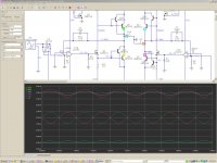
That is not response, it is FFT (spectrum analyzer). Nothing should be there but your test signal, and a very low digital noise floor. There must be a massive DC drift somewhere; this registers incorrectly on the FFT as the slant you see. Try replacing large caps with voltage sources with the same voltage drop.
That is not response, it is FFT (spectrum analyzer).
Yes yes yes. Alien jargons 😀
Nothing should be there but your test signal, and a very low digital noise floor. There must be a massive DC drift somewhere; this registers incorrectly on the FFT as the slant you see. Try replacing large caps with voltage sources with the same voltage drop.
Thanks. Now it looks horrible (I need to work around it a bit to clean up the peaks). Actually we can see the existence of the second and third "peaks" from previous chart. I just didn't understand why the slanting "spectrum" (?).
Do you have a standard regarding an acceptable spectrum? For example (not to mention the order of the distortion):
1) At 1kHz must be below 0dB
2) Above 1kHz "peak" the decays/peaks must be below -100dB
3) At 10kHz must be below -30dB
4) Below 1kHz "peak" the decays/peaks must be below ?
Few minutes ago I played around with Mooly's Hexfet M1 and achieved a "clean" spectrum. Both the M1 Hexfet and this amp have very similar THD spectrum. It is understandable with latfet to get clean spectrum at high frequency, but hexfet??? Hmmm.... that hexfet M1 can be a good sounding amp, because if it can produce good highs, then it is perfect.
Attachments
I have no "standard". The 0db point doesn't really matter much, it is the relative db between the fundamental and harmonics that matters, A 100db difference is .001%THD, regardless of where the fundamental is. Generally you want to test your amplifier with the load and signal level it will be used with during normal listening. Then do "worst case" scenarios, like a drunken party where someone turned the volume all the way up and then stole the knob...
Everything that is not your test frequency or a multiple of your test frequency is not real, it is noise coming from inexact computations in the simulator. So if your test signal is 1KHz, the only valid parts of the FFT will be 1KHz, 2KHz, 3KHz and so on. If your circuit is oscillating that will also be a peak. Anything that goes on before 1KHz is probably DC drift of some sort. In real life there would be interference, infrasonic rumbles maybe, but simulation is rather, shall I say, "hermetic". It is technically impossible for a properly working amplifier in simulation to produce anything that's not drift or a harmonic of the test signal.
To make the noise floor lower, and uncover more "buried" harmonics, you can try this:
.options numdgt=7
Gerald...
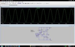
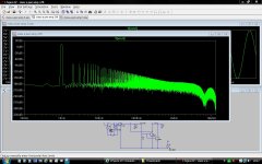
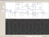
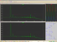
I tried your amp and find it clips on the negative half cycles. I increased the load to 4 ohms but still the same result.
Speaking non Spice now, I feel 2N3055's probably aren't the best choice for driving low load impedances. Also looking at your circuit, in practice the current will be shared unequally between the output transistors due to differences between devices. Maybe look at some form of emitter resistor to help equalise the current.
Again just thinking aloud... perhaps the lack of negative swing is due to the drive requirement of the FET.
Here's the FFT result at lower amplitude.
Attachments
Getting late lol
How does Q5 work now kean ?
Although it works in the simulation, schematically there is no bias to Q5. The emitter is at a higher voltage than the base in the sim 🙂
I'll look again tomorrow 🙂
How does Q5 work now kean ?
Although it works in the simulation, schematically there is no bias to Q5. The emitter is at a higher voltage than the base in the sim 🙂
I'll look again tomorrow 🙂
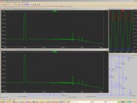
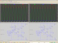
I have done some comparisons of the backwards transistor and I have found some very interesting results.
I don't mean to be off topic here but it is very interesting !
The Sim's show that either configuration works and with the transistor the wrong way the 2nd THD is about 1 to 2 db higher and the 3rd THD is lower than with the transistor going the correct way.
But both show them to be about -90db and lower.
I have done the comparisons in LTspice and Circuitmaker.
In LTspice the first test was with just a reversal of the transistor into 1 ohm with no changes to the circuit.
The next two tests are with the bias currents nearly equal and into 1 ohm and 4 ohms.
The Circuitmaker tests show the test circuit and relations of the output voltage which is the same same for all of the configurations.
The next two tests show a the relationship of the output devices currents for 8 ohms and 2 ohms in Circuitmaker.
It shows that there is a phase reversal of the current in the bottom output transistor as the output impedance gets lower.
But the good thing is that it doesn't effect the output voltage swing and it is where it is supposed to be regardless of the output impedance.
Also as the output impedance get higher the THD gets lower but this is normal.
This is very interesting but very confusing and shows in the LTspice Sim's as well.
The configuration of the transistor does effect the bias currents between the two circuits but I was able to adjust them so that they were equal.
In the Circuitmaker tests it was set it so that each output device was at 3.77 amps and in LTspice it was around the same range although I did not check it for an exact figure.
All of my Circuitmaker examples have the transistor going the right way and it was a fluke on my part that it ended up wrong.
But it did work so it went without being noticed.
It does explain why I had a hard time at first getting it to work due to the higher voltage I needed to get the bias set right.
?????
Anyway as I mentioned didn't mean to go off topic here but this is the first time that I have done this and usually a circuit will either work ,or, not work at all !!
Thanks !
jer 🙂
Attachments
-
 class a amp 3 Q5 vs Q5REV CM currents 2 ohms.jpg102.9 KB · Views: 146
 -
 class a amp 3 Q5 vs Q5REV CM currents.jpg96.2 KB · Views: 131
 -
 class a amp 3 Q5 vs Q5REV CM output voltage.jpg87.7 KB · Views: 165
 -
 class a amp 3 Q5 vs Q5REV CM test circuit.jpg85.1 KB · Views: 179
 -
 class a amp 3 FFT equal currents 4 ohm.jpg72.4 KB · Views: 148
 -
 class a amp 3 Q5 vs Q5REV equal currents 4 ohm.jpg107.1 KB · Views: 153
 -
 class a amp 3 FFT equal currents.jpg71.6 KB · Views: 142
 -
 class a amp 3 Q5 vs Q5REV equal currents.jpg112 KB · Views: 293
 -
 class a amp 3 FFT.jpg74.5 KB · Views: 292
 -
 class a amp 3 Q5 vs Q5REV.jpg109.7 KB · Views: 305
Last edited:
I think the IRF540 provides a constant current to Q5's base, and according to Hfe that becomes a constant (but not really) collector current. It looks like Jay had something else in mind with those diodes though. The output stage of this amp will almost certainly die a quick death from thermal runaway, but it is a good simulator experiment.
I cheated with perfect simulator current sources... It simulates fine this way, just the current source lifts the emitter above the rail. 🙂
I cheated with perfect simulator current sources... It simulates fine this way, just the current source lifts the emitter above the rail. 🙂
Yes Jay, I found simulation fun in the same way you do, it's like intentionally leaving the stove on full blast for a month while your away just to see what will happen, except it's virtual reality and you have nothing to lose. 🙂
Thanks,Mooly, for checking it out!
I had eliminated the emitter resistors in order to see how close to the rails I could get using a 1 ohm load.
I would definitely use some better output devices for sure in a final version as well as many more.
At the time I had came up with this circuit I didn't have other models to work with other than those that came with the programs.
Possibly making this the ultimate Junkbox parts design(he,he).
I have had this concept in mind ever since I first started using Circuitmaker but it has only been until recently that I have been able to understand all of the little things required to make it work.
Yes, being this as a high current Class A design I am concerned about thermal stability and I am still learning.
jer 🙂
I have no "standard". The 0db point doesn't really matter much, it is the relative db between the fundamental and harmonics that matters, A 100db difference is .001%THD, regardless of where the fundamental is. Generally you want to test your amplifier with the load and signal level it will be used with during normal listening. Then do "worst case" scenarios, like a drunken party where someone turned the volume all the way up and then stole the knob...
Everything that is not your test frequency or a multiple of your test frequency is not real, it is noise coming from inexact computations in the simulator. So if your test signal is 1KHz, the only valid parts of the FFT will be 1KHz, 2KHz, 3KHz and so on. If your circuit is oscillating that will also be a peak. Anything that goes on before 1KHz is probably DC drift of some sort. In real life there would be interference, infrasonic rumbles maybe, but simulation is rather, shall I say, "hermetic". It is technically impossible for a properly working amplifier in simulation to produce anything that's not drift or a harmonic of the test signal.
Thanks, Kean. I have learnt a lot from your works. And special post like this teaches me a lot.
About the real worst case schenario testing, I still am confused. Does this mean (0.8) input sine wave (and 3R load)? I have simulated a popular amp with small input voltage (like 0.3) and I found like the output devices being abused??? Or am I just looking at peak power, which is under device's short term capability?
I have also run squarewave (pulse train) to my amps but I haven't seen the normal form of "ringing" but a narrow one (tall line) which I don't know the meaning of. I tried a popular amp and check the result to make sure if it was normal or not, and it seemed it happened to the popular amp also. May be this is another software mishandling issue?
All of my Circuitmaker examples have the transistor going the right way and it was a fluke on my part that it ended up wrong.
But it did work so it went without being noticed.
It does explain why I had a hard time at first getting it to work due to the higher voltage I needed to get the bias set right.
It is possible for a transistor to work even when reversed biased if the conditions are right, although the gain is a low.
I cheated with perfect simulator current sources... It simulates fine this way, just the current source lifts the emitter above the rail. 🙂
OK then 🙂
I have also run squarewave (pulse train) to my amps but I haven't seen the normal form of "ringing" but a narrow one (tall line) which I don't know the meaning of. I tried a popular amp and check the result to make sure if it was normal or not, and it seemed it happened to the popular amp also. May be this is another software mishandling issue?
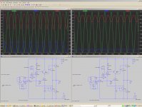
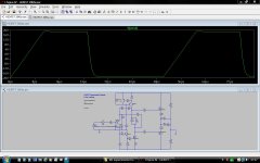
Squarewave testing...
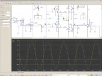
Look at this. Here is the simulation of the amp linked to earlier. Remember I built the amp and tested it for real and the scope shots are for real.
Now compare with Spice. Look at the scope shots on posts #3 and #4 and compare.
http://www.diyaudio.com/forums/soli...-hexfet-poweramp-sonic-benefits-approach.html
Attachments
- Status
- Not open for further replies.
- Home
- Design & Build
- Software Tools
- LTSpice FFT simulation settings and inconsistent results.