on the tht rectifier pcb its still there on bottom as smd foot print. ,
on the smd rectifier pcb, its removed.
on the smd rectifier pcb, its removed.
In this post, I thought you were offering ICs, when I read your previous answer today I figured these were the PCBs. Anyway, do you also offer these chips as well? If not can you or anyone plz direct me where to find the cheapest prices yet reliable source for these ICs.
Kindly find below my order:
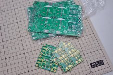
1. CRC PCB: x1 pcs
2. THT PCB: x1 pair
3. SMD PCB: x1 pair
pl pm me your paypal email, complete postal address.
regards
prasi
Will this CT rectifier work or burn??
I have read many many postings, lots of words, but did not find a final answer to my specific question: Will the following configuration work with the 4320 or will it fail?

Please note that the two winding sections are indicated to be wound in sequence (i.e. they are in phase), so my conclusion from previous discussions is that the configuration should work.
So I'm just simply requesting a yes/no answer, as the transformer is what I have (part of a purchased item) and if the answer is no, the diodes rectifier will just stay in place and two secondary winding snubbers will be implemented.
Thanks and Regards,
Winfried
I have read many many postings, lots of words, but did not find a final answer to my specific question: Will the following configuration work with the 4320 or will it fail?
Please note that the two winding sections are indicated to be wound in sequence (i.e. they are in phase), so my conclusion from previous discussions is that the configuration should work.
So I'm just simply requesting a yes/no answer, as the transformer is what I have (part of a purchased item) and if the answer is no, the diodes rectifier will just stay in place and two secondary winding snubbers will be implemented.
Thanks and Regards,
Winfried
Attachments
Hi Dave somehow i missed your post.
here are answers.
Use either R1-R6 or RP1/RP2. effective resistance about 0.1 ohm to 0.33 ohm is a good value for crc type supply.
for 35v secondaries, PB3506 OR PB3508/PB3510 are good. but will need heatsink depending on current demanded from your amp. e.g. for 5 amps, voltage drop in rectifier is ~1.0v , so power dissipated is approx 5W.
for class ab amp and normal listening, you could do away without heatsink.
Blocked
chassis discoonect network ... Power Supply for Power Amplifiers or some use a cl-60 between psu ground and chassis.
RB and RB- you can use 3300ohm also, its not critical. it determines how fast your caps are discharged when powered down.
For the chassis disconnect,
If using dual mono PSU boards, should each board get its own "ground disconnect network" each attached to a common star ground,
Or can one "ground disconnect network" be connected to both boards?

Thank you,
David.
Something like this.. there is no best single solution. depends on how you build it. are they single mono blocks? or everything in same case?
example understanding star grounding
read this excellent article by hifisonix
http://hifisonix.com/wordpress/wp-content/uploads/2019/02/Ground-Loops.pdf
example understanding star grounding
read this excellent article by hifisonix
http://hifisonix.com/wordpress/wp-content/uploads/2019/02/Ground-Loops.pdf
Something like this.. there is no best single solution. depends on how you build it. are they single mono blocks? or everything in same case?
example understanding star grounding
read this excellent article by hifisonix
http://hifisonix.com/wordpress/wp-content/uploads/2019/02/Ground-Loops.pdf
Everything in one case.
Thanks for the links, will read up!
Hi guys, given a transformer AC output, how can I calculate the DC voltage output for a PSU with this rectifier? For normal diode rectifiers the formula is DCV = 1.414 x ACV - 1.414. Can I apply the same formula with lt4320 based rectifiers or is it different?
Thank you very much,
Gaetano.
Thank you very much,
Gaetano.
Yes it is exactly the same. However normally the calculation distracts 2 x Vf of the diodes (the last part 1.414 is normally 2 x 0.7V) which we practically don't have with ideal rectifiers.
The very low Vf like a few tens of mV makes that in practice the theoretical voltage is the result. It would be like DCV = 1.414 x ACV - 0.12. Don't underestimate this as for instance with low power DC power applies one can often choose a lower transformer voltage and reduce losses/heat.
The very low Vf like a few tens of mV makes that in practice the theoretical voltage is the result. It would be like DCV = 1.414 x ACV - 0.12. Don't underestimate this as for instance with low power DC power applies one can often choose a lower transformer voltage and reduce losses/heat.
Last edited:
Ok, then if I use these rectifiers for an amp PSU (e.g. 40VAC input) I can also not consider these few tens mV. Is it right?
Gaetano.
Gaetano.
Hi guys, given a transformer AC output, how can I calculate the DC voltage output for a PSU with this rectifier? For normal diode rectifiers the formula is DCV = 1.414 x ACV - 1.414. Can I apply the same formula with lt4320 based rectifiers or is it different?
Thank you very much,
Gaetano.
You need to take in account the loss over your secondary trafo as well.
Correct formula is Vdc=(1,4142 x Vac) - 2(Rdson x Iload) - (Rsecondary X Iload)
Where:
Vdc - voltage after LT4320 rectifier
Vac - voltage at the secondary trafo with no load connected
Rdson - is the mosfet drain to source resistance at saturation. Usually at Vds > 10V
Rsecondary - Series trafo secondary resistence. In many cases this is higher than mosfet Rdson
Iload - current trough your load
Example:
A trafo that have 9Vac in secondary and able to deliver 5A.
A mosfet with Rdson 6mohm at Vds>6V
A trafo with 300mohm secondary at full load will have after synchronous rectifier:
Vdc = (1.4142 x 9Vac) - 2(0.006ohm x 5A) - (0,3ohm x 5A) = 11,16V
while with a normal bridge you have:
Vdc = (1.4142 x 9Vac) - (2 x 0,7V) - (0,3ohm x 5A) = 9,82V
Regards,
Tibi
I have read many many postings, lots of words, but did not find a final answer to my specific question: Will the following configuration work with the 4320 or will it fail?
Please note that the two winding sections are indicated to be wound in sequence (i.e. they are in phase), so my conclusion from previous discussions is that the configuration should work.
So I'm just simply requesting a yes/no answer, as the transformer is what I have (part of a purchased item) and if the answer is no, the diodes rectifier will just stay in place and two secondary winding snubbers will be implemented.
Thanks and Regards,
Winfried
No, this will not work with LT4320.
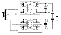
However, I have designed a synchronous bridge that is able to work in any configuration, including centre tapped tafo - look for Saligny HVHF.
Regards,
Tibi
Which Rdson can we consider for this rectifier?
Besides, can it be used with center tapped transformers?
Gaetano
Besides, can it be used with center tapped transformers?
Gaetano
LT4320 can not work with center tapped transformers.
Rdson is a parameter of the mosfet you use in your LT4320 implementation.
Regards,
Tibi
Rdson is a parameter of the mosfet you use in your LT4320 implementation.
Regards,
Tibi
You need to take in account the loss over your secondary trafo as well.
Correct formula is Vdc=(1,4142 x Vac) - 2(Rdson x Iload) - (Rsecondary X Iload)
Where:
Vdc - voltage after LT4320 rectifier
Vac - voltage at the secondary trafo with no load connected
Rdson - is the mosfet drain to source resistance at saturation. Usually at Vds > 10V
Rsecondary - Series trafo secondary resistence. In many cases this is higher than mosfet Rdson
Iload - current trough your load
Example:
A trafo that have 9Vac in secondary and able to deliver 5A.
A mosfet with Rdson 6mohm at Vds>6V
A trafo with 300mohm secondary at full load will have after synchronous rectifier:
Vdc = (1.4142 x 9Vac) - 2(0.006ohm x 5A) - (0,3ohm x 5A) = 11,16V
while with a normal bridge you have:
Vdc = (1.4142 x 9Vac) - (2 x 0,7V) - (0,3ohm x 5A) = 9,82V\
Regards,
Tibi
Thanks for the full calculation where (0,3ohm x 5A) of the transformer of course is equal and normally should be taken into account. The relevant part is the 2(0.006ohm x 5A)= 0.06V or 60 mV which practically can be neglected.
When not using the transformer at full load, which normally isn't done, the practical outcome of Vac x 1.4142 is very close when using LT420 based rectifiers (like ghitus asked). When one calculates by head it will also do with Vac x 1.4 under load thereby distracting some of the losses. When one uses overdimensioned transformers this simple rule of thumb more or less is right in practice with only slight deviations (there is never a calculator nearby when you need it).
Last edited:
LT4320 can not work with center tapped transformers.
Then this design cannot be done with lt4320 rectifiers...

No.
Alternatively, see Variant C on the Saligny Standard datasheet.
https://evotronix.eu/main/wp-content/uploads/2021/01/SalignyS.pdf
Regards,
Tibi
Alternatively, see Variant C on the Saligny Standard datasheet.
https://evotronix.eu/main/wp-content/uploads/2021/01/SalignyS.pdf
Regards,
Tibi

Hi Tibi,No, this will not work with LT4320.
However, I have designed a synchronous bridge that is able to work in any configuration, including centre tapped tafo - look for Saligny HVHF.
Regards,
Tibi
and thanks for your clear answer. The HVHF solution may work, but at the stated cost it seems much more economic for the application to invest into a new 30VA transformer with separate secondary windings. Now, just by pure coincidence, I've just got hold of a separate secondaries transformer matching the application and this way working with the 4320 active rectifiers I already own.
Thanks again,
Winfried
- Home
- Group Buys
- LT4320 based active rectifier