Will a simple DC speaker protection circuit work? I think the ones I use won't connect the speakers until the offset is below 100mV.
Yes, it will work.
The only thing I would test - before connecting a real speaker - is that there will be no "intermediate" attempts to connect the speaker before DC fully settles at the output. As far as I remember from my initial tests, on power-on, DC first goes to the negative rail, then it passes "zero" point and goes to some positive value, and then finally comes to zero. That first zero crossing is rather quick, so I don't think protection will "flicker" on it, but it would be good just to make sure.
Hi Valery,
Will this transformer work?
F14X Triad Magnetics | Mouser
It seems Digikey is out of the one you posted.
Will this transformer work?
F14X Triad Magnetics | Mouser
It seems Digikey is out of the one you posted.
Hi Valery,
Will this transformer work?
F14X Triad Magnetics | Mouser
It seems Digikey is out of the one you posted.
Hi Terry,
Yes, this one will be perfectly fine.
Cheers,
Valery
Still4
I don't know what DC detector circuit you have in your speaker protection.
Many require >700mVdc of offset to trigger.
Some require >2Vdc to trigger.
Have you measured your trigger threshold?
I don't know what DC detector circuit you have in your speaker protection.
Many require >700mVdc of offset to trigger.
Some require >2Vdc to trigger.
Have you measured your trigger threshold?
As an option, I would increase the soft-start time constant (increasing the cap value significantly), so that it makes the initial attempt to connect the speakers not in 2 seconds (as it does in the most of the cases), but in 12-15 seconds.
I agree with Andrew - unless DC sensor is based on the operational amplifier IC, the threshold will most likely not be less than 700mV DC...
I agree with Andrew - unless DC sensor is based on the operational amplifier IC, the threshold will most likely not be less than 700mV DC...
OK, I will have to test mine. I have two different protection circuits. I tested to make sure they worked but dont remember now the exact voltage that turned them on. I know by default that they are off initially at power on. There is a built in delay.
Listening impressions
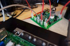
I have finally assembled a simple EF3 power section and auditioned the whole thing. I don't want to be immodest 🙂rolleyes🙂, but it's fantastic.
No doubt, my neighbors had some hard time today 😀 Overall impression - highest clarity and resolution over the whole audio frequency range regardless of the output level even at "difficult" material. Lots of micro-dynamic nuances. Something I did not expect to be special here - accurate, solid, powerful bass. Maybe it's not so much related to its hybrid nature - most likely the reasons are powerful PSU and three Sanken pairs in OPS - I don't know, but that's what it is. Everybody noticed it from the first minutes of listening.
Big Phat Band, Grover Washington (Winelight), Ray Brown Trio (Soular Energy), Bassface Swing Trio (Tribute to Cole Porter), SPL (Surrounded by drums) - all sounded perfectly. In overall, it's comparable with my class-A amp with one advantage - bass is simply the best.
This test confirmed we don't need any regulated DC for the tube heating - the amp is dead quiet with no signal in existing configuration (6.3V AC heating).
Looking forward to see more impressions from the ones who builds it.
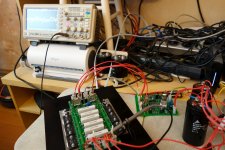
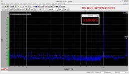
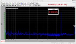
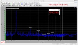
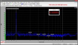
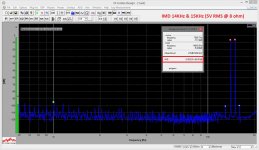
I also attach couple of pictures and some measurements in combination with OPS. Strong dominance of the 2-nd harmonic. 3-rd one is much lower (10-12db), all the rest practically don't exist.
I like it.
Cheers,
Valery
I have finally assembled a simple EF3 power section and auditioned the whole thing. I don't want to be immodest 🙂rolleyes🙂, but it's fantastic.
No doubt, my neighbors had some hard time today 😀 Overall impression - highest clarity and resolution over the whole audio frequency range regardless of the output level even at "difficult" material. Lots of micro-dynamic nuances. Something I did not expect to be special here - accurate, solid, powerful bass. Maybe it's not so much related to its hybrid nature - most likely the reasons are powerful PSU and three Sanken pairs in OPS - I don't know, but that's what it is. Everybody noticed it from the first minutes of listening.
Big Phat Band, Grover Washington (Winelight), Ray Brown Trio (Soular Energy), Bassface Swing Trio (Tribute to Cole Porter), SPL (Surrounded by drums) - all sounded perfectly. In overall, it's comparable with my class-A amp with one advantage - bass is simply the best.
This test confirmed we don't need any regulated DC for the tube heating - the amp is dead quiet with no signal in existing configuration (6.3V AC heating).
Looking forward to see more impressions from the ones who builds it.
I also attach couple of pictures and some measurements in combination with OPS. Strong dominance of the 2-nd harmonic. 3-rd one is much lower (10-12db), all the rest practically don't exist.
I like it.
Cheers,
Valery
Attachments
-
 00-@Tube-01.JPG330.2 KB · Views: 400
 -
 01-@Tube-THD-10k-10v.JPG269.8 KB · Views: 159
 -
 01-@Tube-THD-10k-03v.JPG267.7 KB · Views: 157
 -
 01-@Tube-THD-01k-10v.JPG270.7 KB · Views: 334
 -
 01-@Tube-THD-01k-03v.JPG271.4 KB · Views: 338
 -
 01-@Tube-IMD-14k-15k.JPG278.3 KB · Views: 355
 -
 00-@Tube-02.JPG254 KB · Views: 375
Power section
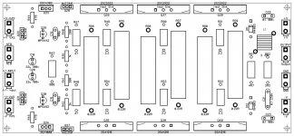
I've got some requests on OPS gerbers.
Here they are along with the parts placement illustration and schematic.
Please note - in the final build I don't use the pre-driver shunt caps. Use them only if necessary.
Cheers,
Valery
I've got some requests on OPS gerbers.
Here they are along with the parts placement illustration and schematic.
Please note - in the final build I don't use the pre-driver shunt caps. Use them only if necessary.
Cheers,
Valery
Attachments
Hi Valery,
Are you saying that there wasn't an issue with offset as the tube warms up?
You mention the high performance that it produces. Have you built any of the other Slewmaster IPS so you can compare it? I've built three of them, five counting the three versions of the CFA. They are all very impressive sonically. I now have all the components for this one but am waiting on the boards. Hopefully they will come this week as I leave on vacation next weekend.
Please let me know what you meant about the offset issues.
Thanks, Terry
Member
Joined 2009
Paid Member
In overall, it's comparable with my class-A amp with one advantage - bass is simply the best.
Congratulations ! 😎
If you have three pairs of output devices with 0R22 resistors and optimal AB bias you will be working with 120mA per output pair, or 360mA total. This will give you Class A operation for 1/2W rms which is probably enough for casual listening 🙂
Hi Valery
Nice looking OPS schematic you have posted. Quite a few differences (and quite a bit simpler) than OStripper's design. I see you have managed to get by without base stoppers in the drivers and pre-drivers. Is the board layout critical to stability? Any chance you could upload an image of the copper?
If its not too much trouble, could you explain your bias spreader?
Cheers
Christian
Power-on and heating
Hi Terry, DC offset at power-on is still an issue. This is the price we have to pay for DC coupling with the tube 🙂
My practical tests show that the best solution is still a soft-start modification in a way that it first powers-on only a 6.3V AC "heating" transformer and after, say, 15 seconds, it continues the normal start-up sequence.
Otherwise, if you just power-on everything at the same time - before the tube heats-up enough, global NFB - and most of compensation - is not working, so there is a chance to see some high frequency oscillation during the first few seconds, which I don't like - dangerous for the power section.
The sentence in a previous post is related to my initial concern, that AC tube heating could induct some 50(60) Hz hum at the input as the heating lines are close to the input circuitry on PCB. Testing confirmed there's nothing to worry about - no hum at all, so using a pure 6.3V AC right from the transformer is fine.
I did not build any of Ostripper's designs (just too busy with my own developments - maybe some day 😉), though I am sure they (both CFAs and VFAs) are very good - OS is a great experienced designer, I like a lot what he is doing.
Cheers,
Valery
Hi Valery,
Are you saying that there wasn't an issue with offset as the tube warms up?
You mention the high performance that it produces. Have you built any of the other Slewmaster IPS so you can compare it? I've built three of them, five counting the three versions of the CFA. They are all very impressive sonically. I now have all the components for this one but am waiting on the boards. Hopefully they will come this week as I leave on vacation next weekend.
Please let me know what you meant about the offset issues.
Thanks, Terry
Hi Terry, DC offset at power-on is still an issue. This is the price we have to pay for DC coupling with the tube 🙂
My practical tests show that the best solution is still a soft-start modification in a way that it first powers-on only a 6.3V AC "heating" transformer and after, say, 15 seconds, it continues the normal start-up sequence.
Otherwise, if you just power-on everything at the same time - before the tube heats-up enough, global NFB - and most of compensation - is not working, so there is a chance to see some high frequency oscillation during the first few seconds, which I don't like - dangerous for the power section.
The sentence in a previous post is related to my initial concern, that AC tube heating could induct some 50(60) Hz hum at the input as the heating lines are close to the input circuitry on PCB. Testing confirmed there's nothing to worry about - no hum at all, so using a pure 6.3V AC right from the transformer is fine.
I did not build any of Ostripper's designs (just too busy with my own developments - maybe some day 😉), though I am sure they (both CFAs and VFAs) are very good - OS is a great experienced designer, I like a lot what he is doing.
Cheers,
Valery
Congratulations ! 😎
If you have three pairs of output devices with 0R22 resistors and optimal AB bias you will be working with 120mA per output pair, or 360mA total. This will give you Class A operation for 1/2W rms which is probably enough for casual listening 🙂
Thank you Gareth

Yes, this is exactly the quiescent current values I use. It may decrease down to around 100 mA per pair for some seconds after the long time listening at high power, which is still ok. And you're right - I had some listening yesterday night, when it was quiet around, so the volume was ok for listening, but my oscilloscope at the output, set to 2V per grid-line, did not show anything most of the time, it still sounded very crisp and natural. Heat dissipation is pretty high though, so a rather large heatsink is required.
Cheers,
Valery
Hi Valery
Nice looking OPS schematic you have posted. Quite a few differences (and quite a bit simpler) than OStripper's design. I see you have managed to get by without base stoppers in the drivers and pre-drivers. Is the board layout critical to stability? Any chance you could upload an image of the copper?
If its not too much trouble, could you explain your bias spreader?
Cheers
Christian
Hi Christian,
Ostripper's design is "less risky", I mean, in terms of possible oscillations, overall stability, etc. This one is a bit more demanding in terms of PCB layout, wiring and so on. However, being handled with care, it shows a good performance and stability.
The bias spreader - I use it in a number of designs already. The first time I have built it - it was fully symmetric, so the top transistor also hat 2k resistor between the base and collector. However, first tests have shown noticeable over-regulation - the spreader appeared to be too sensitive. So I have shortened the top resistor, converting the top transistor into a diode and lowering its thermal sensitivity, so the overall thermal characteristic of the spreader became very close to the optimal one - since that time I have just repeated it a number of times in different designs.
I like the spreader arrangement, used by OS, with one transistor sensing the drivers and the other one sensing the big OP trannies - I will probably try something similar next time...
Images or the copper are attached.
Cheers,
Valery
Attachments
Valery, do you think it would be possible to power this front end with a voltage doubler? I was thinking of running a single pair of outputs with 35V rails with a voltage multiplier to generate the 70V rails for the input stage. Any suggestions?
You use MPSA42/MPSA92 as pre-driver with 330 resistor emitter. Are the pre-drivers dissipation high? It is safe for them?
Valery, do you think it would be possible to power this front end with a voltage doubler? I was thinking of running a single pair of outputs with 35V rails with a voltage multiplier to generate the 70V rails for the input stage. Any suggestions?
Hi Christian, see post #78 by Pawel - HERE - something like this will be ok, just need to be extended to get the negative rail multiplied as well. You will also have to add a baker clamp at the power section input lo limit the front-end output swing. The front-end consumes not more than 40mA from each rail. Looks doable.
You use MPSA42/MPSA92 as pre-driver with 330 resistor emitter. Are the pre-drivers dissipation high? It is safe for them?
Hi Bimo, well noticed - actually, in the final prototype I use 660 ohm (680 ohm will be fine) here. I also use small local heatsinks on pre-drivers - they increase overall thermal stability dramatically, including OPS quiescent current stability. This way MPSA42/MPSA92 feel good 🙂
Attachments
Hi Valery,
I'm expecting my boards tomorrow so I was double checking my parts and realized I don't have the 1N4759. Looks like that is a 62V zener. Does it need to be 1W. I thought I would stack some zeners to get me to 62V but not sure I have all 1W.
Thanks, Terry
I'm expecting my boards tomorrow so I was double checking my parts and realized I don't have the 1N4759. Looks like that is a 62V zener. Does it need to be 1W. I thought I would stack some zeners to get me to 62V but not sure I have all 1W.
Thanks, Terry
Hi Valery,
I'm expecting my boards tomorrow so I was double checking my parts and realized I don't have the 1N4759. Looks like that is a 62V zener. Does it need to be 1W. I thought I would stack some zeners to get me to 62V but not sure I have all 1W.
Thanks, Terry
Hi Terry, in this particular case they operate at 4.5 mA, dissipating 62V * 0.0045A = 0.28W each. So 0.5W zeners, like BZX55C62 for example, will be fine. However, 0.1W ones will overheat.
Cheers,
Valery
- Status
- Not open for further replies.
- Home
- Amplifiers
- Solid State
- Low TIM, low distortion hybrid front-end