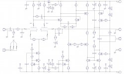
in the schematic just above C4,12 gnd connections should go to the negative rails that each of the ccs are referenced too respectively, instead of gnd
Exactly, see the schematic attached. However, as I mentioned (I even ran a simulation with strong pulsation at negative rail) - assuming we've got rails heavily filtered and high loop gain, this is more of a "potential improvement", so Terry - you can leave the caps as is - up to you.
I will incorporate this change in the next version, combining all possible improvements we discovered recently though.
Jcx - thank you, I actually did not think about it this way, something to keep in mind from now on 😉
I will incorporate this change in the next version, combining all possible improvements we discovered recently though.
Jcx - thank you, I actually did not think about it this way, something to keep in mind from now on 😉
Attachments
Two days - 24/2 😉 - running smoothly
Running it during about 2 days non-stop now. Listening mostly in the mornings and in the evenings, but it's running constantly, playing something all the time.
Still impressed by bass response. It's not about the amount of bass - the amount is like normal, just maybe a bit stronger at the very low end - but more about the quality.
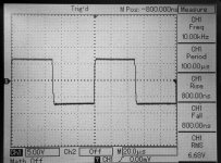
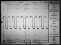
Especially noticeable at Yello's "Motion Picture" album - Track 1 "Get On" and Track 10 "Bubbling Under". Very "clean", solid, pleasant sound. On Track 1, when the bass sounds, oscilloscope at the output shows clean sine wave, somewhere between 20 and 40 Hz, depending on the note played. Definitely synthesized - sounds perfectly
Running it during about 2 days non-stop now. Listening mostly in the mornings and in the evenings, but it's running constantly, playing something all the time.
Still impressed by bass response. It's not about the amount of bass - the amount is like normal, just maybe a bit stronger at the very low end - but more about the quality.
Especially noticeable at Yello's "Motion Picture" album - Track 1 "Get On" and Track 10 "Bubbling Under". Very "clean", solid, pleasant sound. On Track 1, when the bass sounds, oscilloscope at the output shows clean sine wave, somewhere between 20 and 40 Hz, depending on the note played. Definitely synthesized - sounds perfectly
Member
Joined 2009
Paid Member
Also think about a hybrid as a next project.
Good! - I'd like to see more hybrids. It almost seems there is a burst of interest around here in such things too.
Garret I posted the schematic you asked me at the other hybrid project. Can you take a look please
I do love the triple darlington power section, I'm not sure about the front (driver stage).
Thank you
These hybrid has a nice front end but with NFB, I'm not sure if I can bring that two together.
I do love the triple darlington power section, I'm not sure about the front (driver stage).
Thank you
These hybrid has a nice front end but with NFB, I'm not sure if I can bring that two together.
Good! - I'd like to see more hybrids. It almost seems there is a burst of interest around here in such things too.
Yeah, I'm also interested in cool ideas in this area. BTW, already moving ahead with "No GNFB" one. Got most of the components, designing the PCBs. Going to be fun 😉
Garret I posted the schematic you asked me at the other hybrid project. Can you take a look please
I do love the triple darlington power section, I'm not sure about the front (driver stage).
Thank you
These hybrid has a nice front end but with NFB, I'm not sure if I can bring that two together.
I looked at that schematic - there's no global NFB there as far as I can see and from the posts at Hungarian forum it looks like it performs very well. Front-end output stage looks rather high-current - small value resistors for such a high voltage rail. It's a pity I've got no models for those tubes - would be interesting to see what simulation shows... I will look for the models though - sometimes I manage to find some on the net.
Cheers,
Valery
Thank you Valery
Yes you right that has no NFB. I thought to combine that power stage with your driver.
The designer of that hybrid told me to wait until he test other driver stage to may be can get even better result.
The power stage (triple darlington) is superior based on the test he made and after several days listening.
Definitely I would love to build some hybrid.
Greetings Gabor
Hi Valery,
I got home today so I implemented the changes you suggested. As before, the IPS seems fine on its own. Plays squared wave and is clean. I then hooked up the OPS through a light bulb tester. The light bulb shines brightly so I began measuring. The light bulb will only allow the rails to come up to +20,-17V. NFB is -14.7. ND- is -15.2 PD+ is -16V. The vbe bias adjustment doesn't work at all with this IPS attached. Voltage across a pair of the .22R output emitter resistors measures 80mv and not matter how I adjust the pot is just stays there. This OPS works fine with all the other Ostripper IPS units. If I get a chance I will build one more using your the latest schematic and see if I can get that to work.
I got home today so I implemented the changes you suggested. As before, the IPS seems fine on its own. Plays squared wave and is clean. I then hooked up the OPS through a light bulb tester. The light bulb shines brightly so I began measuring. The light bulb will only allow the rails to come up to +20,-17V. NFB is -14.7. ND- is -15.2 PD+ is -16V. The vbe bias adjustment doesn't work at all with this IPS attached. Voltage across a pair of the .22R output emitter resistors measures 80mv and not matter how I adjust the pot is just stays there. This OPS works fine with all the other Ostripper IPS units. If I get a chance I will build one more using your the latest schematic and see if I can get that to work.
Last edited:
Now I'm certainly puzzled...
Terry, there is one more option to try. A bit over-compensated, but absolutely stable in my environment. No C15, C18 = 150pF, C14 = 47pF (schematic from post #182).
At the same time I will talk to Jason regarding PCBs to reproduce the Slewmonster - this is getting interesting...
Cheers,
Valery
Terry, there is one more option to try. A bit over-compensated, but absolutely stable in my environment. No C15, C18 = 150pF, C14 = 47pF (schematic from post #182).
At the same time I will talk to Jason regarding PCBs to reproduce the Slewmonster - this is getting interesting...
Cheers,
Valery
I think I will wait for you to get a Slewmaster OPS. The pads and traces are tiny on these boards. I don't want to chance ruining them with all these changes. I will try populating one more board with the schematic for post #180 as well as make the changes you just suggested. It may take a few days because I think I'm out the proper values for the 1W resistors.
On another note. The speaker protection circuit I use is attached. Which caps do I change to delay the switch on further?
Thanks, Terry
On another note. The speaker protection circuit I use is attached. Which caps do I change to delay the switch on further?
Thanks, Terry
Attachments
Now I'm certainly puzzled...
Terry, there is one more option to try. A bit over-compensated, but absolutely stable in my environment. No C15, C18 = 150pF, C14 = 47pF (schematic from post #182).
At the same time I will talk to Jason regarding PCBs to reproduce the Slewmonster - this is getting interesting...
Cheers,
Valery
Hey Valery,
Just PM me regarding the SlewMaster OPS, we can figure something out.
I think I will wait for you to get a Slewmaster OPS. The pads and traces are tiny on these boards. I don't want to chance ruining them with all these changes. I will try populating one more board with the schematic for post #180 as well as make the changes you just suggested. It may take a few days because I think I'm out the proper values for the 1W resistors.
On another note. The speaker protection circuit I use is attached. Which caps do I change to delay the switch on further?
Thanks, Terry
Hi Terry,
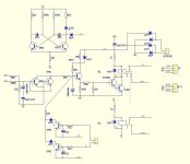
In this schematic, RC combination is responsible for setting the right time constant and though speaker-on delay (68K resistor and 220uF capacitor - within the red box).
Brief calculation shows that 220K and 1000uF will give you some 20-30 seconds delay. Please test practically for exact values.
Cheers,
Valery
Attachments
No NFB OPS / Nested NFB options
Hi Terry,
With help from Jason, I am ordering the Slewmonster PCBs, so hope to look at the issue closer pretty soon.
At the same time, if you're up to couple of experiments - not dangerous and "non-invasive" for the boards, here are two options to test:
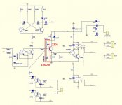
1) No NFB for OPS (Picture 1). Put two 2.2k resistors, right underneath the board, as shown on the picture. Don't connect NFB plug to OPS.
With no NFB, OPS will not influence stability, so the whole thing should work the same way as there's no OPS connected. Don't forget to re-bias the OP.
THD will increase, though it will still be within 0.05% if biased properly (80-90 mA per output pair).
IF 1-st OPTION WORKS FINE, YOU CAN PROCEED TO THE SECOND ONE.
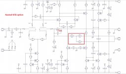
2) Nested NFB (Picture 2). Change R13 to 100k and arrange another 100k with two 2.2k resistors as shown on the picture. Connect NFB wire to OPS as usual.
This option covers OPS with very light NFB (around 6 db), giving better THD than the previous one, while not jeopardizing stability (at least it should not).
I am running the 2-nd option on my test bench at the moment - no audible difference with the original design.
This may be used as an interim solution until I find the cause of an issue.
Cheers,
Valery
Hi Terry,
With help from Jason, I am ordering the Slewmonster PCBs, so hope to look at the issue closer pretty soon.
At the same time, if you're up to couple of experiments - not dangerous and "non-invasive" for the boards, here are two options to test:
1) No NFB for OPS (Picture 1). Put two 2.2k resistors, right underneath the board, as shown on the picture. Don't connect NFB plug to OPS.
With no NFB, OPS will not influence stability, so the whole thing should work the same way as there's no OPS connected. Don't forget to re-bias the OP.
THD will increase, though it will still be within 0.05% if biased properly (80-90 mA per output pair).
IF 1-st OPTION WORKS FINE, YOU CAN PROCEED TO THE SECOND ONE.
2) Nested NFB (Picture 2). Change R13 to 100k and arrange another 100k with two 2.2k resistors as shown on the picture. Connect NFB wire to OPS as usual.
This option covers OPS with very light NFB (around 6 db), giving better THD than the previous one, while not jeopardizing stability (at least it should not).
I am running the 2-nd option on my test bench at the moment - no audible difference with the original design.
This may be used as an interim solution until I find the cause of an issue.
Cheers,
Valery
Attachments

Member
Joined 2009
Paid Member
It seems a shame to have to try different OPS to get this stable. The original design looks good and has been shown to work. There could be some variations between parts - the parasitic capacitances of the tubes (try different tubes ?), sockets, heater wiring, general wiring and speakers and power supplies etc. etc. Maybe one of the compensation caps is 'bad'. I wonder if it isn't worth trying to tweak the compensation of the baseline design a bit more, pull down the OLG at higher frequencies a bit more aggressively. It may not be where you want to go long term but short term it might provide something that is working and can be improved on further. And then you can compare the two OPS for sound rather than introducing another variable into the detective story at this early stage ??
How much voltage does this output?
Highly linear up to 120V peak-to-peak (42.5V RMS).
Clips nicely at 126V peak-to-peak (44.5V RMS). No saturation or artifacts.
- Status
- Not open for further replies.
- Home
- Amplifiers
- Solid State
- Low TIM, low distortion hybrid front-end