Please post the schematic. As I said, there are many variants flying around that are losing this feature in the process of "improving" it. One good example above.
Yes true, but in this Hawskford circuit the Cart is driving the bases.
I used a transconductance variant that was driving emitters as in Bonsai's circuit.
Caps were used connected to the bases, that discharged partly over the Cart at switch off.
When driving bases, there is usually no need to construct additional complex circuitry to protect the Cart.
Hans
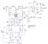
Here is the schematic for one channel of the 'TranBal MC Head Amp'.
I have not added the CM adj. pot. If people feel strongly about it, I will add it. The BW limiting cap (C8) is 12nF and not 6nF (5.6nF) to save on an additional value - at 20kHz we are only down by 0.2 dB. 12nF will be used in the RIAA EQ section.
I am pushing the LM4562 a bit with the +5V reg (25mA load current worst case) so I am proposing to have the output at c. 10-12V off a 15V rail and to drop the voltage down to 5V through a 270 Ohm resistor. The +5V Ultra rail is heavily filtered (1000uF) similar to the X-Altra MC/MM.
I've used 100 Ohm 0.1% 0805 and 1k 0.1% 0805 - when you buy them 10 up the cost comes down quickly.
Most of the remaining values (and in the RIAA MM section to come) will be based on values I'm currently using and have to hand.
I'll post up the RIAA + filter section tomorrow
As always, comments/feedback welcome
Attachments
Last edited:
I would love to see a formal explanation for this.
It’s simple, you missed the context.
The input signal is effectively swinging the floating power supply above and below through a load resistor. You see a related technique in power amplifiers where the output is grounded and the load is connected to the power supply 0 V. The amplifier PSU rails swing the PSU rails which swings the 0 V point and hence develops a voltage across the load.
Last edited:
The input signal is effectively swinging the floating power supply above and below through a load resistor. You see a related technique in power amplifiers where the output is grounded and the load is connected to the power supply 0 V. The amplifier PSU rails swing the PSU rails which swings the 0 V point and hence develops a voltage across the load.
Is this in reply to my question and does the explanation
apply to "all" phono stages with "floating" supply ? Your
power amp example, known with dual floating supplies,
allows dc output also, otherwise, where would be the low
corner frequency ? Thanks.
The example in post 115 has the Hawksford drawing style.
Maybe, but it looks like the worse of all worlds: complex, floating power supplies (plus cell charging switching), cartridge current. I don't see any benefit over what Hans/Bonsai suggested here.
I may be wrong, but I thought I mentioned the LFD principle, as illustrated in the link I provided, not a specific screwed up implementation, be it Hawksford or not.
And in that lost context, post 101, you made the floating supply
and zero current through the cartridge under all conditions claim
and zero current through the cartridge under all conditions claim
Whatever, this doesn't make the schematic you posted less of a dumb implementation of a valid principle.
I posted the schematic in reply to mkc's finding who cited you (context).
And again, the claim, repeated frequently, is not substantiated.
And again, the claim, repeated frequently, is not substantiated.
Is anybody interested in the original text "LFD MC Preamplifier 1988" ?
I can find no adequate thread for it.
I can find no adequate thread for it.
And again, the claim, repeated frequently, is not substantiated.
You already mentioned this 4 times, keep trying please.
Is anybody interested in the original text "LFD MC Preamplifier 1988" ?
https://www.researchgate.net/profil...638/Audio-Amplifier-Systems-A-Compilation.pdf
About half down.
- Home
- Source & Line
- Analogue Source
- Low noise Balanced MC Pre