Hi all, the prototype works well. I built only one channel and intensively tested in the last months. I've found one issue, it's not stable in class AB mode (idle cc 60mA per pair, ltspice does not show any problems). Class B mode is OK, see the link below.
Now I begin to design a new symmetrical pcb, maybe helps to fix the class AB.
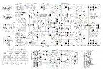
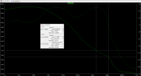
Notice the nested feedback and OITPC compensated outer loop. The inner loop uses comp caps from output to the unity gain OPS VAS input.
LeXaN - Google Photos


Now I begin to design a new symmetrical pcb, maybe helps to fix the class AB.
Notice the nested feedback and OITPC compensated outer loop. The inner loop uses comp caps from output to the unity gain OPS VAS input.
LeXaN - Google Photos
Attachments
Last edited:
Hi Ladislav,
Excellent work. Innovative design. Nice build. Nice test results.
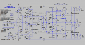
Just curious, the "Xcond 40mA" on the 1v0 schematic, is that measured? If so, what conditions?
I have found cross-conduction on my Linear Audio v13 amp was worst case with no load, and near full output swing at 100kHz sine. But check cross-conduction both no load and normal load.
Also, how do you bias this amp for Class-AB? Do you have a sim' circuit to share as you mentioned it sim'ed OK in Class-AB.
Excellent work. Innovative design. Nice build. Nice test results.
Just curious, the "Xcond 40mA" on the 1v0 schematic, is that measured? If so, what conditions?
I have found cross-conduction on my Linear Audio v13 amp was worst case with no load, and near full output swing at 100kHz sine. But check cross-conduction both no load and normal load.
Also, how do you bias this amp for Class-AB? Do you have a sim' circuit to share as you mentioned it sim'ed OK in Class-AB.
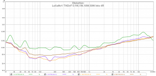
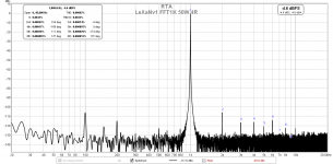
Hi LKA, nice job! I am thinking about the "curls" that are repeated at 50 Hz multiples in your
https://www.diyaudio.com/forums/att...ut-stage-lexanv1-thdvf-0-1w-1w-10w-50w-4r-png
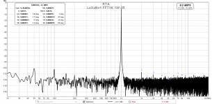
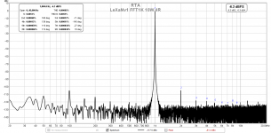
measurement. Could you please post a spectral plot of 1kHz sine, 4ohm load at 1W or 5W? How is the power supply ripple rejection, is it OK?
https://www.diyaudio.com/forums/att...ut-stage-lexanv1-thdvf-0-1w-1w-10w-50w-4r-png
measurement. Could you please post a spectral plot of 1kHz sine, 4ohm load at 1W or 5W? How is the power supply ripple rejection, is it OK?
Hi LKA, nice job! I am thinking about the "curls" that are repeated at 50 Hz multiples in your
https://www.diyaudio.com/forums/att...ut-stage-lexanv1-thdvf-0-1w-1w-10w-50w-4r-png
measurement. Could you please post a spectral plot of 1kHz sine, 4ohm load at 1W or 5W? How is the power supply ripple rejection, is it OK?
Hi Pavel,
I would like your opinion about OITPC used by some smart people here in this forum. Cordell did not find a time for that even if he promised to take a look.
OITPC - Output inclusive TPC (not TMC)
BR Damir
Hi LKA, nice job! I am thinking about the "curls" that are repeated at 50 Hz multiples in your
https://www.diyaudio.com/forums/att...ut-stage-lexanv1-thdvf-0-1w-1w-10w-50w-4r-png
measurement. Could you please post a spectral plot of 1kHz sine, 4ohm load at 1W or 5W? How is the power supply ripple rejection, is it OK?
Hi PMA, thanks
I know, PSRR is not the best, used front-end has quite low rejection ratio at low frequencies. I will double(triple) C24,25 capacity on the new pcb, hope it helps.
Attachments
Hi Ladislav,
Excellent work. Innovative design. Nice build. Nice test results.
Just curious, the "Xcond 40mA" on the 1v0 schematic, is that measured? If so, what conditions?
I have found cross-conduction on my Linear Audio v13 amp was worst case with no load, and near full output swing at 100kHz sine. But check cross-conduction both no load and normal load.
Also, how do you bias this amp for Class-AB? Do you have a sim' circuit to share as you mentioned it sim'ed OK in Class-AB.
Hi Ian, thanks.
Xcond is simulated parameter, I will try to measure it (oscilloscope with floated ground or battery powered).
Class AB biasing is easy, short out the D17 and D18. In the evening (CET time) I will post the sim file.
Hi Ladislav,
Great job - very nice OPS arrangement.
I'm very interested to know if there is some OPS input impedance "modulation" depending on the output swing - my gut feeling it must be good (rather low), I'll try to check that soon in simulation.
Cheers,
Valery
Great job - very nice OPS arrangement.
I'm very interested to know if there is some OPS input impedance "modulation" depending on the output swing - my gut feeling it must be good (rather low), I'll try to check that soon in simulation.
Cheers,
Valery
Hi PMA, thanks
I know, PSRR is not the best, used front-end has quite low rejection ratio at low frequencies. I will double(triple) C24,25 capacity on the new pcb, hope it helps.
Hi, this looks fine re PSRR.
I've found one issue, it's not stable in class AB mode
This might be an issue (probably higher BW of the output stage with higher idle current and higher Gm in the doubled-Gm area) and I would recommend to play with FB compensation network. Did you make stability tests with the complex load? Non-resistive load should be tested as well, IMO.
Lexan Class-AB bias simulation
Hi Ladislav,
Thanks for posting the Class-AB modifications to convert from Class-B low bias (1mA) current driven to Class-AB optimum biased at approx 60mA.
The simulation shows the idle current does increase from 60mA at start to when running warm.
To get your simulation to work I added the BD139 bias sensor temperature code (T4). The updated file is attached. Run it and change T3 (power transistor Tj) from 25C to say 35C and watch the idle current. (Don't use the usual ".Temp 25 35" card as this only used for global changes).
To get this simulation to reflect your amp you need to estimate the thermal attenuation factor - the ratio of sensor temperature to the power transistor Tj -- likely to be in the range of 0.5 to 0.7. It depends on heatsink size.and thermal insulator efficiency, and how close the bias sensor is to the power transistors. Bob Cordell explains it in his book.
How to get your amp Class-AB idle current stable with warm up? One way is to move the sensor transistors and mount them on top of the power transistors cases. It may fix the bias drifting up.
Try the attached simulation with a thermal attenuation factor of 0.8 (sensor on top) then 0.5 which maybe your original amp mounting arrangement. (The thermal attenuation factor is in the T4 equation).
Attachments
Hi, I tried and found a small mistake
.param T4=0*(T3-25)*0.5+25
should be
.param T4=(T3-25)*0.5+25
0.22R emitter resistors fix the thermal runaway problem in classAB, sensing transistors can stay on the main heatsink.
.param T4=0*(T3-25)*0.5+25
should be
.param T4=(T3-25)*0.5+25
0.22R emitter resistors fix the thermal runaway problem in classAB, sensing transistors can stay on the main heatsink.
Lexan Class-B and Class-AB switch
Hi Ladislav,
Nice work🙂.
Will you be posting measurements for the Lexan with Class-AB bias?
Have you listened to the amp in Class-B? In Class-AB? You should be able to now do a listening comparison switching between Class-B and Class-AB (by shorting the base diodes).
BTW with mono listening, if you don't label the switch and hide the wiring so you and others can't see, then you can do a double blind comparison to make the outcome more meaningful.
As I wrote earlier (post #21) the amp is oscillating in AB mode. 20 seconds after power up the F4A fuses blow.
See the youtube video LeXaN AB oscillation - YouTube
Test conditions : input shorted, unloaded output
Oscillation at output: start 3Vpp 15MHz, end 1.5Vpp 13MHz
See the youtube video LeXaN AB oscillation - YouTube
Test conditions : input shorted, unloaded output
Oscillation at output: start 3Vpp 15MHz, end 1.5Vpp 13MHz
Last edited:
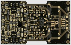
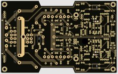
Congrats Laco. What is the sonic advantage compared to Danwatt?The redesigned pcb is finished. I also changed the outer (global) loop compensation scheme to TMIC.
I'm really happy with the new design.
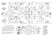
Predriver transistors (T9, T10) and the outputs are working on same load. In crossover region the drives bypass the output trans, so you can set the outputs nearly in pure Class B with very low crossover distortion. At least as I understand it. Am I correct, laco?
Looks nice and interesting, what's the main advantage of this topology?
It's Class B (with distortion of Class AB), so output transistors idle current is minimal (< 1mA, with R30-32 biasing cca 3mA). Optimally biased AB has idle heat dissipation 10-20W per channel, here less than 1W. Even when I listen to music the heatsink remains at room temperature.
- Home
- Amplifiers
- Solid State
- Low distortion current driven Class-B output stage