I have repeatedly suggested push-pull Class A for output op amps in a composite to turn PP rail currents very nearly linear and therefore their coupling effects largely (very small) gain errors
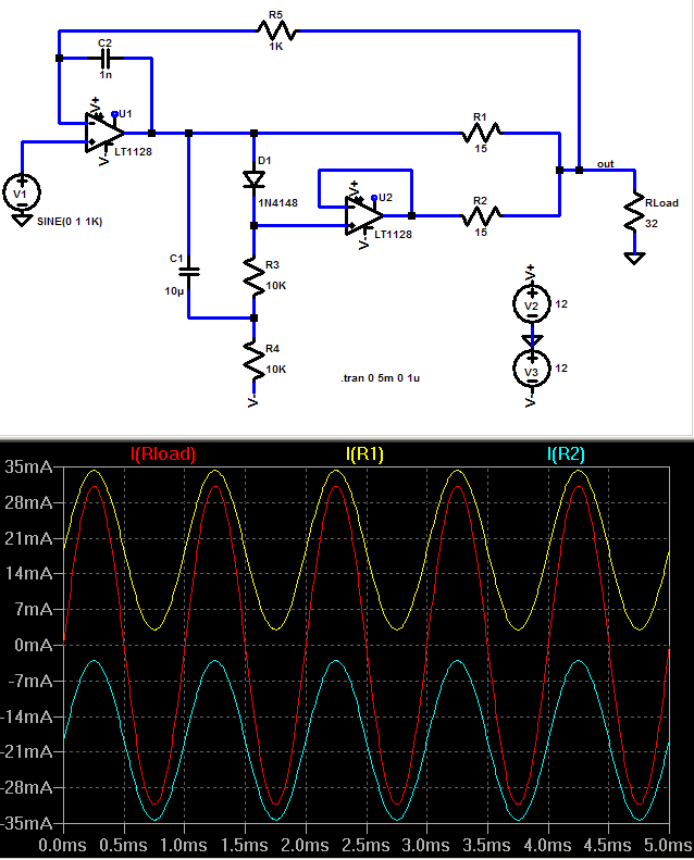
Interesting but the question is if the cure is worse than the disease? The voltage drop across the diode even with the DC bias and bypass is not perfectly constant!
I saw something is one of the amp threads about stacking opamps literally and getting "improved sound". Two were good, three were better but 4 got too hot. I think its a poor implementation of the push pull class A idea, assuming its not just oscillating. If you counted on offset differences between opamps and used 5 ohm balancing resistors you may get similar results with lots less circuitry, possibly lower noise as well.
I don't think class D has crossover issues. So why the class A.
Class D will not influence the sound to much, I hope, as it will play a power supply role. The sound will be result of analog amp, Class A or B(AB).
BTW I remembered I still have a Boonton 1130 analyzer I am not using. Anybody interested for a reasonable price?
Note that this is the analyzer portion of an 1120, without the generator but with all the notches and auto tuning/ranging etc.
I also have some spare boards for it.
It is fully functional.
Jan
Note that this is the analyzer portion of an 1120, without the generator but with all the notches and auto tuning/ranging etc.
I also have some spare boards for it.
It is fully functional.
Jan
Class D will not influence the sound to much, I hope, as it will play a power supply role. The sound will be result of analog amp, Class A or B(AB).
Yes good. Kind of like throwing in one tube in the solid state change.
Luxman come to mind.
Hi Jan,
You should be able to find a taker for it on your side of the pond. There must be a needy DIYer near you.
Very kind of you to offer that for reasonable money.
-Chris
You should be able to find a taker for it on your side of the pond. There must be a needy DIYer near you.
Very kind of you to offer that for reasonable money.
-Chris
I don't think class D has crossover issues. So why the class A.
PWM Class D does indeed have crossover distortion. I discuss it in my book. It has to do with things like dead time to prevent totem-pole conduction.
Cheers,
Bob
PWM Class D does indeed have crossover distortion. I discuss it in my book. It has to do with things like dead time to prevent totem-pole conduction.
Cheers,
Bob
I see.
Well at the time class D kind of sucked. So I didn't read that chapter.
However I will read it in you new addition. I thought that issue had be solved.
Back on topic. One member here (slartibartfasst) has taken his Viktor oscillator powered by a SilentSwitcher to the good AP people and has send me some graphs, see attached. Apologies for the less than optimal quality.
In the time-based graph you see a spike at around 21 seconds, this is of course not a freq line but a power supply drop-out due to the flakey power switch that was used. So disregard that.
He noted that with the SilentSitcher at 30V total supply, the THD +N was about half the spec with the recommended 36V supply. Food for thought.
Jan
Attachments
Last edited:
Back on topic. One member here (slartibartfasst) has taken his Viktor oscillator powered by a SilentSwitcher to the good AP people and has send me some graphs, see attached. Apologies for the less than optimal quality.
In the time-based graph you see a spike at around 21 seconds, this is of course not a freq line but a power supply drop-out due to the flakey power switch that was used. So disregard that.
He noted that with the SilentSitcher at 30V total supply, the THD +N was about half the spec with the recommended 36V supply. Food for thought.
Jan
I can see it won't stabilize at 30. All that noise on the left.
I can see it won't stabilize at 30. All that noise on the left.
You mean the 60Hz and up? That cannot come from the supply, as the SilentSwitcher was powered by a battery.
Quote:
"One, the SilentSwitcher was powered by a battery pack that I had previously blown up and puts out a noisy ~4V over a USB-A connector. Your switcher puts out a clean 30.15V from this unworthy supply, so I threw the pack, the oscillator and the switcher in my pocket.
Two: I forgot the "enable" jumper on my other SilentSwitcher. To enable the supply I used the clip on a lanyard the event supplied to hold name-tags. The AP guys were very nice about all this. However, I bumped the lanyard (I think) at 20s into the test, so there is a pulse where the Switcher powers down and powers back up, gracefully. "
I hesitate to say this, but it is either mains hum picked up by test leads or - gasp - residual from the AP...
Jan
Anyway relatively impressive result. Hum and noise at the low side maybe if the oscillator runs without an enclosure. But, I am surprised about the AP's ADC possibilities. Also interesting spike at the 16kHz region.
You mean the 60Hz and up? That cannot come from the supply, as the SilentSwitcher was powered by a battery.
Quote:
"One, the SilentSwitcher was powered by a battery pack that I had previously blown up and puts out a noisy ~4V over a USB-A connector. Your switcher puts out a clean 30.15V from this unworthy supply, so I threw the pack, the oscillator and the switcher in my pocket.
Two: I forgot the "enable" jumper on my other SilentSwitcher. To enable the supply I used the clip on a lanyard the event supplied to hold name-tags. The AP guys were very nice about all this. However, I bumped the lanyard (I think) at 20s into the test, so there is a pulse where the Switcher powers down and powers back up, gracefully. "
I hesitate to say this, but it is either mains hum picked up by test leads or - gasp - residual from the AP...
Jan
I'm not talking about power supply junk. The spectrum on the left is what I get if the oscillator is not getting 36 or more volts. It won't settle properly.
This is a combination of directly measured spectrum (for fundamental) and spectrum after notch filter (for harmonics). I don't know how AP aligns both measurements.But, I am surprised about the AP's ADC possibilities.
I also thought about this 🙂This is a combination of directly measured spectrum (for fundamental) and spectrum after notch filter (for harmonics). I don't know how AP aligns both measurements.
I have noticed that the distortion of Victor's oscillator drops with level. If the supply is reduced to +/- 12V I suspect the output voltage would drop as well.
Adequate shielding to get rid of stray power line noise is quite involved. Mine are all in a cast aluminum box but on some tests I need to put the box in another box tied to the reference ground to get the external hum and noise out, even with shielded cables.
Adequate shielding to get rid of stray power line noise is quite involved. Mine are all in a cast aluminum box but on some tests I need to put the box in another box tied to the reference ground to get the external hum and noise out, even with shielded cables.
I'm not talking about power supply junk. The spectrum on the left is what I get if the oscillator is not getting 36 or more volts. It won't settle properly.
Maybe Viktor can shed some light on this. Both my oscillators (1k and 5k) work fine at 30V
Jan
Maybe Viktor can shed some light on this. Both my oscillators (1k and 5k) work fine at 30V
Jan
Are you bypassing the 100 ohm resistors.
I thought Victor specified 35Vdc minimum. Even at 35V I've had unusual noise in the low band. Raise the supply to 36V and it all disappears.
The oscillators can run from 30V, but onboard shunt stabilizers +/-15 do not work in this situation. +/- supply wires go to a lower level, and also output goes lower, because the AGC system gets reference voltage from the -15V wire. Oscillator can work until the AGC can control the FET. Typically the FET needs -3V...-7V (depending of example). The system works until the AGC can produce this voltage. This means, that the minus supply voltage must be for some volts higher then the FET control voltage. Old model oscillators have the divider at the FET gate, and as result, AGC needs higher voltage for to run.Maybe Viktor can shed some light on this. Both my oscillators (1k and 5k) work fine at 30V
Jan
Also, when undervoltage applies, then the load resistance at output can affect to onboard supply with further consequences.
You can observe when AGC system goes out of control - when the supply goes down, but output starts to rise.
Last edited:
One other point and maybe Victor can comment on this.
I believe the shunt regulators also generate a virtual ground in Victor's design.
If the supply voltage is lower than what the shunt regulators are programed for
then what happens to the virtual ground? Can the shunts generate a low Z ground if the supply is not enough for them to function?
Jan are you replacing the generator's ground with the ground of your switcher.
If so then this should work. But if it's single supply connected then maybe not.
- Home
- Design & Build
- Equipment & Tools
- Low-distortion Audio-range Oscillator