Let's talk about the use and need for guarded circuits, inputs and guard shields and driven shields.
??
THx-RNMarsh
I said to a class mate when we were introduced to driven shields that if you drive a capacitor with the same potential at each end the capacitor doesn't do anything.
Since a coax cable is mostly capacitance...
I don't think he got it.
Last edited:
Let's talk about the use and need for guarded circuits, inputs and guard shields and driven shields.
??
THx-RNMarsh
It very much depends on where in the circuit you are addressing issues. High impedance nodes are sensitive to stray cap and coupling so they do benefit from a driven shield. Also high Z DC sensitive circuits benefit. Low Z not so much. In these oscillators I have not seen many places where they would be important. High Z locations would also be noise sources. Make the impedances low for that to go away. Also switching etc. may need driven shields to reduce capacitive coupling that is not wanted.
There is a distortion cancelling trick for state variable audio oscillators like the ebay one being discussed here. It uses the state variable section as both an oscillator and a filter simultaneously. It requires an additional opamp and two or three resistors. It is described by Ian Hickman in one of his books and a couple of Electronics and Wireless World articles. I can dig up the references if anyone is interested.
A reference to an article by Hickman in" Electronics World", issue August 1999, was made in post #73 of this thread.
Regards,
Braca
Regards,
Braca
The distortion cancellation is discussed on p302 of "Analog Electronics" by Ian Hickman ( 1993/1994 paperback edition ) with a circuit diagram. I also have references to EWW April '92 p345 and May'94 p370 in my notes but I haven't checked yet to see if they explicitly relate to distortion cancellation.
There's also Bruce Hofer's US patent No.4,560,958 from 1985.
Note the phase shift oscillator in Post #1 of this thread has a very effective 3rd harmonic cancellation circuit.
Nothing new here, it's all been covered before in this thread.
Note the phase shift oscillator in Post #1 of this thread has a very effective 3rd harmonic cancellation circuit.
Nothing new here, it's all been covered before in this thread.
Both the EWW articles relate to low distortion oscillators. The first discusses the distortion cancellation in detail and shows you how to do it with only two resistors to sum the weighted HP and LP outputs of the state variable sections if you really can't afford an extra opamp. The second describes a SV oscillator with a different amplitude stabilization method using an LM13600.
EssB - you're right the Hickman distortion cancellation method is similar, but not identical, to that in post #1. However I was merely trying to point out that this technique is a simple add on to the low cost ebay 1kHz oscillator and could all but eliminate the residual 3rd harmonic distortion.
Jim Williams pdf can now be found @Found the links to the Jim Williams AN 43.
http://cds.linear.com/docs/Application Note/an43f.pdf
Reading Jim Williams: App Note 43 part 1
http://cds.linear.com/docs/en/application-note/an43f.pdf
All three parts are in the one pdf AN43
Been looking through the Wurcer LNA courtesy of Xen.
Question 1.)
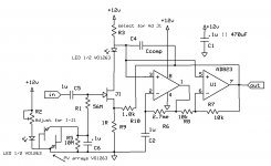
The PV array is shown in the sch with the outputs in parallel but in opposite directions. This is replicated in the PCB.
If I set the 10kVR LED current into the PV Array and assume this is fixed.
When the input jFET draws current, it turns on the other LED and generates an opposite output, thus reducing the net voltage/current fed to the input offset injection via the 56Meg resistor.
If the jFET draws more current, the offset current injection is reduced.
Am I interpreting this correctly?
Q2.)
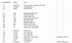
The R2a value is shown as 3k ±0.5%.
This resistor is in series with the 10k VR.
Why is a 0.5% tolerance resistor specified?
Q3.)
The 10k R7 R8 and the 1r R9 are specified as Vishay S102.
What do these resistor do that needs this quite specific resistor.
Can any 1r and 10k metal film be substituted?
If not any, what parameters are important for selecting these resistors?
Q4.)
C4 is optional and a 5pF is suggested. A position is not shown on the PCB. Where should this be located?
Question 1.)
The PV array is shown in the sch with the outputs in parallel but in opposite directions. This is replicated in the PCB.
If I set the 10kVR LED current into the PV Array and assume this is fixed.
When the input jFET draws current, it turns on the other LED and generates an opposite output, thus reducing the net voltage/current fed to the input offset injection via the 56Meg resistor.
If the jFET draws more current, the offset current injection is reduced.
Am I interpreting this correctly?
Q2.)
The R2a value is shown as 3k ±0.5%.
This resistor is in series with the 10k VR.
Why is a 0.5% tolerance resistor specified?
Q3.)
The 10k R7 R8 and the 1r R9 are specified as Vishay S102.
What do these resistor do that needs this quite specific resistor.
Can any 1r and 10k metal film be substituted?
If not any, what parameters are important for selecting these resistors?
Q4.)
C4 is optional and a 5pF is suggested. A position is not shown on the PCB. Where should this be located?
Last edited:
I looked back through the last month of posts and could not find it.Not familiar with this. Can yo provide a link.
Now I'm beginning to believe it's from another Thread.
But when I enter Wurcer + Xen into search there is only this Thread reported.
I'll keep looking. I know it's somewhere, because I bought a PCB from Xen.
I can't find the correct Thread.
But I did download the BoM and sch
Can anyone recognise these and help point me to where they came from?
But I did download the BoM and sch
Can anyone recognise these and help point me to where they came from?
Question 1.)
The PV array is shown in the sch with the outputs in parallel but in opposite directions. This is replicated in the PCB.
If I set the 10kVR LED current into the PV Array and assume this is fixed.
When the input jFET draws current, it turns on the other LED and generates an opposite output, thus reducing the net voltage/current fed to the input offset injection via the 56Meg resistor.
If the jFET draws more current, the offset current injection is reduced.
Am I interpreting this correctly?
Q2.)
The R2a value is shown as 3k ±0.5%.
This resistor is in series with the 10k Variable R2.
Why is a 0.5% tolerance resistor specified?
Q3.)
The 10k R7 R8 and the 1r R9 are specified as Vishay S102.
What do these resistor do that needs this quite specific resistor.
Can any 1r and 10k metal film be substituted?
If not any, what parameters are important for selecting these resistors?
Q4.)
C4 is optional and a 5pF is suggested. A position is not shown on the PCB. Where should this be located?
Attachments
Last edited:
Hi Andrew,
It's from this thread:
http://www.diyaudio.com/forums/soli...1000-low-noise-measurement-amp-ikoflexer.html
It's from this thread:
http://www.diyaudio.com/forums/soli...1000-low-noise-measurement-amp-ikoflexer.html
If one wants a low distortion of .005x% THD (16bit), you can just buy a Hamtek HDG2012B and get a function/arbitrary generator thrown in.
IMO---cheap for all it does --- $279.
THx-RNMarsh
IMO---cheap for all it does --- $279.
THx-RNMarsh
If one wants a low distortion of .005x% THD (16bit), you can just buy a Hamtek HDG2012B and get a function/arbitrary generator thrown in.
IMO---cheap for all it does --- $279.
THx-RNMarsh
Qingdao Hantek Electronic Co., Ltd.
Regarding the BNC in/out of the FREX osc and erms.
What is the difference between isolated BNC and not isolated?
bnc_coude_bld1 & bnc_coude_iso1
this type name does not appear in the Farnel website.
What is the difference between isolated BNC and not isolated?
bnc_coude_bld1 & bnc_coude_iso1
this type name does not appear in the Farnel website.
non isolated bnc is one that the mounting flange is the outside case or coax shield.
73K1442 73K1441
isolated bnc is one where the mounting flange is not connected to the coax shield or connectors shell.
78M7243
lots of them
Right Angle Bulkhead Jack RF Connectors | Newark element14 Canada
73K1442 73K1441
isolated bnc is one where the mounting flange is not connected to the coax shield or connectors shell.
78M7243
lots of them
Right Angle Bulkhead Jack RF Connectors | Newark element14 Canada
- Home
- Design & Build
- Equipment & Tools
- Low-distortion Audio-range Oscillator