Hi Bob,
The system zero doesn't necessarily have to be zero volts. In the case of using an ADC for the a sampler the ADC I'm using has a range of 0 to xV. Even if a bias is placed on the ADC input to give it a +/- range the zero is the mid code of the ADC regardless of input range. There is no reason why an analog sampler can't be set up with a non zero volt system zero. You would just have to bias the proportional amplifier and integrator the same. I think with a bit of creative design you could use the principle with a conventional peak detector by scaling the system zero.
Not sure that answers the question, but I'll keep scratching my head. I think the essence of my question is independent of where the system zero is in a conventional rectifier-based amplitude detector.
Cheers,
Bob
This introduces a time lag (phase shift) into the amplitude control loop. More significantly, the track-hold must remain in "hold" mode until the sample-hold finishes acquiring the sample, and only then can the track-hold start to track the signal again. This means the amount of phase shift in the amplitude control loop will be frequency dependent. That by itself isn't a catastrophe, but it DOES require some thought and attention when designing the loop. Intuitively I think a bigger problem is that, for a given oscillator frequency, the time delay between sample updates will have a +/- 1 oscillator period variation - depending on whether the sampling pulse ends just before, or just after, the track-hold would normally be returned to "track" mode.
Are you referring to the width of the sampling pulse that controls the sample-hold acquisition time? Shortening that pulse at higher oscillator frequencies would seem to introduce a frequency-dependent amplitude error. The amount of error is essentially predictable, so it could be compensated in the system design, but that would be a notable increase in complexity.
Somewhere in this thread I believe somebody mentioned that one of the high performance oscillators - either one of the AP's, or a Krohn-Hite - used that approach rather effectively. I think they even mentioned the commercial IC type that was used, though the parts required some kind of screening or selection for the oscillator to meet spec.
I've had the same thought. I think I estimated about $75 worth of good (not great) small-signal relays to do a pair of 10-bit DAC's. And about an acre of PWB to mount them on.
Yeah, that sweep capability - or the ability to quickly (milliseconds) shift between frequencies - is an exciting idea. In his thesis paper, Samuel said that integrated MDAC's, and even FET-switched discrete DAC's, caused too much distortion for the performance level he was striving for. He may have alluded to some preliminary experiments that supported this claim, but I don't think he mentioned any measured values.
Did you mean "see it", or "hear it"? That conjures up visions of the few times I was inside a telephone central office (CO) in the days of electromechanical switching. Clickety-clackety-kachunk! I was only in CO's with crossbar switches, though I once saw a small PBX with a step-by-step rotary switch. The telco inside-plant guys said a step-by-step CO was deafening at peak hours.
If I had seen that technique before (and it seems like I should have encountered it at some point in the last half century or so), I have forgotten it. Samuel did a great job of pointing out the advantages - including the fact that the error signal you want to find and process becomes a variance from zero volts, rather than a small deviation riding on top of a larger level.
Dale
"This introduces a time lag (phase shift) into the amplitude control loop."
Yes it does but it works anyway. I had my sampler running at every forth cycle. It takes longer to settle but it does settle with the same stability. At high frequencies the longer settling time is not so noticeable. I haven't come to any conclusion with the idea that sampling less often maybe less of a disturbance to the oscillator resulting lower distortion.
"In the system one and with my oscillator the timer (mono) is reset on the edge of the zero crossing detector. If the period of the frequency is shorter than the fixed pulse width of the mono the reset shortens the pulse width."
I didn't state this properly. The sampling in my oscillator in done with an ADC. The sample rate of the ADC is much higher than the highest frequency the oscillator runs at. The reset of the mono one shot only effects the gating of the pulsed integrator. At high frequencies above 10kHz the pulse duration to the integrator becomes a 50% duty cycle at the same frequency of the oscillator.
"Are you referring to the width of the sampling pulse that controls the sample-hold acquisition time? Shortening that pulse at higher oscillator frequencies would seem to introduce a frequency-dependent amplitude error. The amount of error is essentially predictable, so it could be compensated in the system design, but that would be a notable increase in complexity."
Compensation would be necessary. It could take the form of switching in smaller caps in the track and hold sample and hold circuit. This would shorten the acquisition time.
Somewhere in this thread I believe somebody mentioned that one of the high performance oscillators - either one of the AP's, or a Krohn-Hite - used that approach rather effectively. I think they even mentioned the commercial IC type that was used, though the parts required some kind of screening or selection for the oscillator to meet spec.
Mdac work very effectively. I haven't observed any increase in distortion compared to resistive tuning in this oscillator. But then this oscillator does not reach the target SG specifies. But darn close.
"Yeah, that sweep capability - or the ability to quickly (milliseconds) shift between frequencies - is an exciting idea. In his thesis paper, Samuel said that integrated MDAC's, and even FET-switched discrete DAC's, caused too much distortion for the performance level he was striving for. He may have alluded to some preliminary experiments that supported this claim, but I don't think he mentioned any measured values."
I'm using two Mdacs in parallel for each section. In theory this should lower the noise and distortion but it does increase noise from the switching. Most of the time the switches are static. I am also concerned with the increase of noise gain. The Mdac present a constant load on the driving op amp and a dynamic load on the input of the following integrator. More interestingly the Mdac present a code dependent capacitance at their output in the neighborhood of 200pF. In parallel 400pF. This limits the smallest value of cap which can be used for the integrator.
"It would be interesting to see a sweep using relays"
Yes I meant hear it. Actually if the sweep was fast enough one would only hear the first and last relay. The others wouldn't do anything.
"If I had seen that technique before (and it seems like I should have encountered it at some point in the last half century or so)"
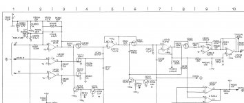
From the SYS1 SM.
"When the leveler has established a stable level for the oscillator the output of the second sample and hold will be zero. This is because the peaks of the sine wave have been made equal to the reference."
Attachments
Not sure that answers the question, but I'll keep scratching my head. I think the essence of my question is independent of where the system zero is in a conventional rectifier-based amplitude detector.
Cheers,
Bob
A conventional rectifier based amplitude detector doesn't provide a low impedance path to discharge the storage cap just a forward path and only when the peak of the signal exceeds the voltage across the storage cap, Can you arrange a circuit that can provide a low impedance bidirectional path triggered by the signal itself.
I showed a simple circuit last year that comes close to that. I'll see if I can find the post.
I just meant zero volts wouldn't be useful because it can't forward bias a diode.
A conventional rectifier based amplitude detector doesn't provide a low impedance path to discharge the storage cap just a forward path and only when the peak of the signal exceeds the voltage across the storage cap, Can you arrange a circuit that can provide a low impedance bidirectional path triggered by the signal itself.
Exactly my point. It seems that the circuit that provides the low impedance bidirectional path is essentially a sample/hold (in this case a S/H controlled by the signal). So I think we are agreeing that an ordinary rectifier amplitude detection circuit has no means to discharge the storage capacitor, and therefore needs some kind of a pull-down (which will establish the ripple amplitude), so the trick does not work in this case.
BTW, it would seem that with the quadrature signal readily available in an SVO, one could use a zero-crossing detector on the quadrature signal to turn on a JFET switch between the main signal and the storage cap, forming a S/H.
Cheers,
Bob
See post 526. if the gap can be filled it might be a workable system.
Exactly my point. It seems that the circuit that provides the low impedance bidirectional path is essentially a sample/hold (in this case a S/H controlled by the signal). So I think we are agreeing that an ordinary rectifier amplitude detection circuit has no means to discharge the storage capacitor, and therefore needs some kind of a pull-down (which will establish the ripple amplitude), so the trick does not work in this case.
BTW, it would seem that with the quadrature signal readily available in an SVO, one could use a zero-crossing detector on the quadrature signal to turn on a JFET switch between the main signal and the storage cap, forming a S/H.
Cheers,
Bob
Maybe I'm not following you here but isn't that how it done in SVO? Detect the zero crossing of the quadrature and open/close switches to caps.
On the ripple amplitude, SG devised a method to make the ripple component in an SH common mode. Can we do the same with a conventional peak detector with pull down on the cap, make the ripple common mode?
I was thinking about this for a while myself. On first glance it doen't make sense however if you take into consideration how the zero tempco foil resistors are made it can make sense.
What they are is a strain gauge bonded to a surface that has an effective expansion with temperature that compensates for the change in resistance of the foil with temperature. When the thermals are changing slowly (DC) or quickly enough to be integrated (mid audio) it could work really well (and it does). For that frequency range where the resistor is continuously changing at a rate similar to the time constant of the substrate you can see how it may actually amplify the changes.
The only real option then are the evenohm wirewound precision resistors. They can be made to be accurate (.01%) to well past 100 K. The cost makes naked Vishay's seem cheap. I know of one source today: Resistors - Oil Filled - Epoxy Encapsulated | Ohm-Labs, Inc.
I never much liked the audiophile favorite 'naked' foil resistors because they look flimsy and lack mechanical damping, as well as thermal. Oil-filled bulk foil resistors might mitigate power coefficient, but totally violate my budget coefficient. 🙁 Probably an issue in common sub-quarter-watt metal films too, which is why some recommend half watt resistors. Not a big issue until one is attempting to minimize every possible source of distortion.
Maybe I'm not following you here but isn't that how it done in SVO? Detect the zero crossing of the quadrature and open/close switches to caps.
The Boonton 1120 uses an SVO. This relatively simple track and hold, sample and hold circuit works in the Boonton 1120 up to 140 KHz with almost unmeasurable amplitude variation. The two inputs are the outputs of the two phases. I'm sure there are better S&H chips available today. It tracks cycle to cycle and seems to work from 10 Hz to 140 KHz with no change in cap values. I suspect a better integrator would reduce any ripple induced by the circuit. In terms of flatness I need to use a thermal converter to check it.
I have a sample and old circuit from an Optimation AC calibrator from 1973 that is more complex, mostly discrete with two opamp modules and I may be able to find the older Krohn Hite 4024 oscillator manual that also used the S&H solution. I don't see a lot to be learned but I'll share if anyone is interested.
I think the Fluke 510 is already up here somewhere. it also uses sample and hold circuits.
I just don't see other solutions used in the higher performance oscillators.
However with a little software the ADC solution could work really well since it could be peak sensitive, timing insensitive and have no issues with discharging a cap. I would not use zero because that's where the ADC's have trouble. Move off of zero as your reference and all should be fine.
Attachments
I had my sampler running at every forth cycle. It takes longer to settle but it does settle with the same stability. At high frequencies the longer settling time is not so noticeable. I haven't come to any conclusion with the idea that sampling less often maybe less of a disturbance to the oscillator resulting lower distortion.
I haven't looked at it mathematically but I think it is near-equivalent to reducing the gain of the leveling loop.
Samuel
I haven't looked at it mathematically but I think it is near-equivalent to reducing the gain of the leveling loop.
Samuel
It has that behavior.
The Boonton 1120 uses an SVO. This relatively simple track and hold, sample and hold circuit works in the Boonton 1120 up to 140 KHz with almost unmeasurable amplitude variation. The two inputs are the outputs of the two phases. I'm sure there are better S&H chips available today. It tracks cycle to cycle and seems to work from 10 Hz to 140 KHz with no change in cap values. I suspect a better integrator would reduce any ripple induced by the circuit. In terms of flatness I need to use a thermal converter to check it.
I have a sample and old circuit from an Optimation AC calibrator from 1973 that is more complex, mostly discrete with two opamp modules and I may be able to find the older Krohn Hite 4024 oscillator manual that also used the S&H solution. I don't see a lot to be learned but I'll share if anyone is interested.
I think the Fluke 510 is already up here somewhere. it also uses sample and hold circuits.
I just don't see other solutions used in the higher performance oscillators.
However with a little software the ADC solution could work really well since it could be peak sensitive, timing insensitive and have no issues with discharging a cap. I would not use zero because that's where the ADC's have trouble. Move off of zero as your reference and all should be fine.
I not sure I understand the software bit or the peak sensitivity. Do you mean it's alignment with the peak? Sampling at the peak is not so important. Always sampling at the same phase of the sine is important. Anywhere between 80 and 110 degrees would work equally as well. Any phase shift will result in a level error. Some advantages of using an ADC for sampling are no droop from cap discharge. A sample can be held indefinitely. No feed through or step compensation is required, all of that is build int and taken care of. Scaling is simple.
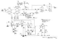
The ADC I'm using is the LTC1609. It's equipped with an SPI transmitter. The transmitter is connected directly to an AD5543 16 bit Mdac that has an SPI receiver. All the glue logic is contained in the ADC. The two together make up what's referred to as an infinite sample and hold. It's simple no software or uP required and has all the flexibility needed to use it as a controller. The ADC has a maximum input range of +/- 25 volts peak to peak. The Mdac can take the same on it's reference pin without destroying it. The devices were intended for instrumentation. Having done this once I don't think I would do it any other way.
Since only the peak is sampled there is no Nyquist limit to be concerned with. The ADC can be used right up to it's rated sample rated of 200ksps. If more band width is needed then use a faster sampler. ADCs are plentiful and have definitely reached SOTA.
The point I was making about the zero is the zero in the controller is a matter of reference not an absolute zero voltage. The zero at the input of the ADC I use is 2.5Vdc. This sets the zero at 32768 which is mid code of 16 bits. The absolute zero is restored at the Mdac
by the dc reference voltage and a bias current at the IV convertor input node.
I've included a schematic of the SVO control.
Attachments
- The R/2R inherently offers the distortion-reduction effect of resistors in series
- For a DIY or even low-volume commercial constructor, it's easier to obtain precision step sizes at lower cost: you buy a moderate quantity (say, 100 pieces) of resistors with the same nominal value, and use pairs in either series or parallel to get the 2:1 ratio for the "R" and "2R" legs. Of course you can manually measure parts to get a matched set, but the purchased lot would almost certainly come from the same manufacturing run so I suspect that even parts rated for 1% tolerance would be closely enough matched to give 8-bit, and perhaps even 10-bit, precision in the R/2R ladder without ANY sorting or measurements.
- The R/2R network offers a much smaller variation of impedance versus value of the digital tuning word, both as the load impedance to the previous (driving) stage, and as the source impedance for the integrator opamp.
Be careful, if you buy 1% parts they are likely to have a gap in values because the manufacturer will likely remove the 0.5% parts.
It is cheaper for him to do selection of precision parts rather than make them.
So, from the 1% parts he is likely to pull the .5% values out.
He may also pull the .1% values from the batch.
That will leave you with 1% to .5% available on either side.
Therefore you should test your values to make sure they are in the desired range.
I'm sure there are better S&H chips available today.
There are very few S&H chips left on the market today. I read in a white paper from AD that the reason S&H ICs were plentiful is because the manufactures couldn't place them in the ADC IC. This is no longer the case.The S&H have been moved into the ADC ICs and is the reason why S&H ICs are vanishing.
There are very few S&H chips left on the market today. I read in a white paper from AD that the reason S&H ICs were plentiful is because the manufactures couldn't place them in the ADC IC. This is no longer the case.The S&H have been moved into the ADC ICs and is the reason why S&H ICs are vanishing.
The A/D's are almost all CMOS based and use architectures where a classic S&H would not be needed anyway. A classic S&H at the 24bit level would be an exercise in futility.
The A/D's are almost all CMOS based and use architectures where a classic S&H would not be needed anyway. A classic S&H at the 24bit level would be an exercise in futility.
I Guess LT was pumping there product then. It was one of their white papers I was reading on infinite sample and hold That made that claim not AD.
I Guess LT was pumping there product then. It was one of their white papers I was reading on infinite sample and hold That made that claim not AD.
They don't have anything in the catalog but those flying cap CMOS switches, I was thinking a useful S&H for an audio A/D.
I'll see if find that paper. I came across it more than a year ago in my search for S&H IC's.
I probably have my facts wrong.
This is the LT paper but I see it's not the one I gave reference to about the disappearance of SH IC's. Maybe it was an AD paper.
http://cds.linear.com/docs/en/lt-journal/Sample-and-Hold_1100_Mag.pdf
I found it. This is the one.
http://www.google.com/url?sa=t&rct=...woDQBQ&usg=AFQjCNFv2b8vFCt4ZkwJ9hkY66IPBH2LeA
Cheers,
Last edited:
I'll see if find that paper. I came across it more than a year ago in my search for S&H IC's.
I probably have my facts wrong.
This is the LT paper but I see it's not the one I gave reference to about the disappearance of SH IC's. Maybe it was an AD paper.
Cheers,
Funny the A/D - DAC S&H was my first thought, pretty limited uses.
- Home
- Design & Build
- Equipment & Tools
- Low-distortion Audio-range Oscillator