Do you mean this one?
The Effect of u-Circuit Non-Linearity
on the Amplitude Stability of RC Oscillators
http://www.hpl.hp.com/hpjournal/pdfs/IssuePDFs/1960-04.pdf
Yes, the math here is very difficult remember this predates computers. Jim Williams sent me this with the comment that he thought this was the best analysis of a basic circuit concept that he had ever seen.
Last edited:
It's a very nice looking board:
[3rd round] AN67 Ultra-low THD 10kHz sine oscillator PCB Group buy. - Discussion Page 10 - diyAudio
He did a great job. It's designed to fit into a specific chassis. It's certainly the highest performance Wein bridge in the known world.
Dirk
However, builders are having problems with it, as mentioned in the discussions section. This doesn't look like an easy oscillator to make stable. They tried to use it for different frequencies also with not so good results. I imagine anything with 180dB of gain would be an oscillating nightmare.
@dirkwright -- the gain and phase responses were specifically tailored for operation at 10kHz -- doing other frequencies would be a significant engineering project, I think.
OK, Glen is getting a group buy together for his generator boards, which are part of his THD analyzer project I've posted on here before.
Who would like an ultra-low distortion audio oscillator PCB? - Page 1
He is in OZ.
Who would like an ultra-low distortion audio oscillator PCB? - Page 1
He is in OZ.
@dirkwright -- the gain and phase responses were specifically tailored for operation at 10kHz -- doing other frequencies would be a significant engineering project, I think.
Yeah, you are right. I don't know what they did with it to try to make it produce different frequencies. There's not enough detail in the thread that I can see.
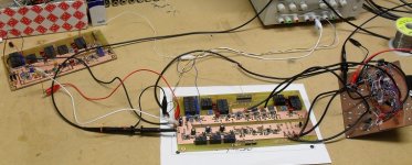
Glen's oscillator
"The notch filter & distortion amplifier PCB is the board in the middle. The board to the left is the state variable oscillator board and the "dead bug" rats nest to the right is the prototype auto-tune board."
From Glen's website. The generator board looks nice and compact, perfect for a rack mount box.
Attachments
Yes, the math here is very difficult remember this predates computers. Jim Williams sent me this with the comment that he thought this was the best analysis of a basic circuit concept that he had ever seen.
HI Scott,
Dick Moore and I were discussing this article recently. Both Dick and myself have worked with lamp stabilized oscillators using op amps. I have done it successfully with a state variable oscillator with remarkable results. Distortion levels as good or better than any other SVO.
Although Dick has witnessed the effect in an original Hp oscillator, neither one us have observed the effect with amplifiers having near pure spectral power.
Why is this?
Cheers,
Last edited:
HI Scott,
Dick Moore and I were discussing this article recently. Both Dick and myself have worked with lamp stabilized oscillators using op amps. I have done it successfully with a state variable oscillator with remarkable results. Distortion levels as good or better than any other SVO.
Although Dick has witnessed the effect in an original Hp oscillator, neither one us have observed the effect with amplifiers having near pure spectral power.
Why is this?
Cheers,
The lamp has two non-linearities, the thermal one and a voltage coefficient of resistance. Measure the lamp's distortion at 10kHz by comparing it to a resistor. The voltage coefficient of non-linearity is what actually stabalizes the oscillation with the thermal one setting the amplitude.
Try a sim with a perfect amplifier, Wein network, and a very small third order non-linearity in the amplifier. Kick it with a current pulse and the oscillation builds up to an amplitude determined by the non-linearity alone. The oscillator has a complex pair of poles that "walk" back and forth on the axis according to the instantaneous gain (gain of exactly 3 is on the axis) . The instantaneous gain is perturbed by the small nonlinearity and the amplitude is stable when the integrated gain over one cycle is exactly 3. Now keep decreasing the non-linearity and the amplitude keeps rising. A low frequency amplitude control is also needed.
I have tried to make a Wein bridge oscillator with no nonlinearity (<-140dB) in the circuit, indeed it never stabalizes except for a few seconds at a time.
Last edited:
Interesting--do you knwo an explanation why the lamp has significant voltage coefficient? So far I've suspected that this is mostly a well behaved metal wire.
Samuel
Samuel
Residual Harmonic Distortion of Viktors Mickevics's 1kHz Oscillator
Hi,
I had a chance to hook Viktors' 1kHz Oscillator on the AP and compare it against AP's own generator (direkt GENMON routing) and the Tek SG505. Test level was 2.7Vrms (Full scale on Victors')
No shielding of the Osc, and fed by lab supply.
The results speak for themselves, or in one word : INCREDIBLE!
Only with massive synchronuous averaging (4096 runs, checked for no/little loss of harmonics magnitudes) it was possible to see the distortion of this oscillator and it fares better than AP's by 10dB...15dB. The SG505 (with only 1024 blocks averaged) is far behind and plaged by hum which also seemed to disturb the autotracking of the notch filter of the AP.
Attachments
@Scott Wurcer -- thanks for the clear explanation about the voltage coefficient of resistance. I wasn't aware of this effect and had only considered the thermal response.
Like Sam, I was thinking of it as a coiled up coil of wire whose inductance and capacitance were too small to care about, leaving thermal response as the only and dominant issue.
Like Sam, I was thinking of it as a coiled up coil of wire whose inductance and capacitance were too small to care about, leaving thermal response as the only and dominant issue.
Interesting--do you knwo an explanation why the lamp has significant voltage coefficient? So far I've suspected that this is mostly a well behaved metal wire.
Samuel
I don't know, I did all this work on the oscillator Jeff Smith and I did (you know the Bateman one 🙄) I can't tell you how much time was wasted. I measured the lamp Jim Williams used and the high frequency distortion checked with the results of the whole circuit. Try the sim, with a simple third order compressive nonlinearity, you get a Q and amplitude stabilization just like with the AGC loop.
I tried the two op-amp Wein bridge with two 797's stabilized by a Tellabs precision wire wound PTAT (-3000ppm/C) resistor which has unmeasurable voltage coefficient at these levels. The output drove a little heater on the resistor. I could not tame the slow wander but when it locked in it was something else. Years later I asked Jim about the distortionless oscillator with a distortion trim, that's when he admitted that the distortion is trimmed below the noise floor citing the Oliver paper.
Last edited:
The lamp has two non-linearities, the thermal one and a voltage coefficient of resistance. Measure the lamp's distortion at 10kHz by comparing it to a resistor. The voltage coefficient of non-linearity is what actually stabalizes the oscillation with the thermal one setting the amplitude.
Try a sim with a perfect amplifier, Wein network, and a very small third order non-linearity in the amplifier. Kick it with a current pulse and the oscillation builds up to an amplitude determined by the non-linearity alone. The oscillator has a complex pair of poles that "walk" back and forth on the axis according to the instantaneous gain (gain of exactly 3 is on the axis) . The instantaneous gain is perturbed by the small nonlinearity and the amplitude is stable when the integrated gain over one cycle is exactly 3. Now keep decreasing the non-linearity and the amplitude keeps rising. A low frequency amplitude control is also needed.
I have tried to make a Wein bridge oscillator with no nonlinearity (<-140dB) in the circuit, indeed it never stabalizes except for a few seconds at a time.
You may be interested in what I'm doing right now. I'd like to share it with you but it's a novel idea and I'd rather not post it here until all my work is complete.
I don't mind email exchange.
I had a chance to hook Viktors' 1kHz Oscillator on the AP and compare it against AP's own generator (direkt GENMON routing) and the Tek SG505. Test level was 2.7Vrms (Full scale on Victors')
No shielding of the Osc, and fed by lab supply.
The results speak for themselves, or in one word : INCREDIBLE!
Only with massive synchronuous averaging (4096 runs, checked for no/little loss of harmonics magnitudes) it was possible to see the distortion of this oscillator and it fares better than AP's by 10dB...15dB. The SG505 (with only 1024 blocks averaged) is far behind and plaged by hum which also seemed to disturb the autotracking of the notch filter of the AP.
Wait a minute--what analyzer settings did you use to get these plots? Can you post a screenshot or e-mail me the setup file?
A SYS-2722 has no way to directly measure distortion below -130 dB with any reasonable uncertainity.
Samuel
I used massive time domain averaging (the full max of 4096 blocks, took several minutes to record) to discard some 20dB of noise/hum. I'll email you the setup tomorrow when I'm back at work, at least the genmon trace should be replicable (though we have outboarded the xformer to get the noise floor as low as possible). Any double-checking is appreciated.Wait a minute--what analyzer settings did you use to get these plots? Can you post a screenshot or e-mail me the setup file?
A SYS-2722 has no way to directly measure distortion below -130 dB with any reasonable uncertainity.
Samuel
I used massive time domain averaging (the full max of 4096 blocks, took several minutes to record) to discard some 20dB of noise/hum. I'll email you the setup tomorrow when I'm back at work, at least the genmon trace should be replicable (though we have outboarded the xformer to get the noise floor as low as possible). Any double-checking is appreciated.
The plot seems to show 155 db notch depth. Is that real, or software?
I have never been able to duplicate the averaging noise reduction they get with other systems.
The lamp has two non-linearities, the thermal one and a voltage coefficient of resistance. Measure the lamp's distortion at 10kHz by comparing it to a resistor. The voltage coefficient of non-linearity is what actually stabalizes the oscillation with the thermal one setting the amplitude.
Try a sim with a perfect amplifier, Wein network, and a very small third order non-linearity in the amplifier. Kick it with a current pulse and the oscillation builds up to an amplitude determined by the non-linearity alone. The oscillator has a complex pair of poles that "walk" back and forth on the axis according to the instantaneous gain (gain of exactly 3 is on the axis) . The instantaneous gain is perturbed by the small nonlinearity and the amplitude is stable when the integrated gain over one cycle is exactly 3. Now keep decreasing the non-linearity and the amplitude keeps rising. A low frequency amplitude control is also needed.
I have tried to make a Wein bridge oscillator with no nonlinearity (<-140dB) in the circuit, indeed it never stabalizes except for a few seconds at a time.
Thank you Scott.
I quickly measured distortion of a small (10r cold resistance) lamp I had around (NOS replacement for Tek 7k scopes) and I've not been able to find any voltage coefficient effects. With 0 dBu across the lamp, distortion (pure 3rd) was -100 dB at 5 kHz. This falls at exactly 20 dB/decade, e.g. at 500 Hz I measured -80 dB. No flattening out at high frequencies was detectable--above the audio band distortion drops below the SYS-2722 residual.
So far it looks to me that all I've seen is pure thermal stuff. It's surprising at what high frequencies one still sees them. Perhaps there are lamps with different behaviour. I'll check if I find another one to measure.
Samuel
So far it looks to me that all I've seen is pure thermal stuff. It's surprising at what high frequencies one still sees them. Perhaps there are lamps with different behaviour. I'll check if I find another one to measure.
Samuel
Last edited:
- Home
- Design & Build
- Equipment & Tools
- Low-distortion Audio-range Oscillator