... In fact the bandwidth of the sample and hold amplifier can track the oscillator frequency for optimum noise performance--see the AP System One schematics for a possible basic implementation.
Part of the attraction of a sample and hold was to eliminate the need for the leveller subsystem to be fine tuned in line with the oscillator frequency, and now I learn this.
Back to the "sum of squares" method.😉
Has anybody in this thread read the Bruce Hofer conference paper that presents the case for the superiority of the State Variable?
The Wein analysis looks to have a mistake, not sure if this is reflected in the final results.
Was there ever an errata or discussion of this?
Best wishes
David
You don't have to go to the extreme of Hoffer's design. You can band limit with an LP at the output. Besides a current drive sets up an LP pole. The pole is a moving target while the oscillator is settling but once settled....
You will have to deal with wide band noise no matter what you do.
Last edited:
You don't have to...
Indeed you don't, or, of course, you can choose to optimize either method as the frequency varies, that's why I put a smiley. But I didn't realize that the sample and hold had sufficient twitches to make the extra complexity worth it.
I still plan to try the sum-of-squares first, simply switch the leveler time constant(s) with the low frequency decades.
Don't see sufficient benefit to adjust continuously as frequency is swept.
Best wishes
David
I built something like this 35 years ago, but today, well, on Amazon you can still buy "2207" generators for about $15, but I would go with a "DDS" box. Have a read about DDS chips, very cool idea. You can buy a $22 dds box but I would spring the $79 for the Kuman FY2202SP
https://www.amazon.com/s/ref=nb_sb_...&field-keywords=DDS+Function+Signal+Generator
https://www.amazon.com/s/ref=nb_sb_...&field-keywords=DDS+Function+Signal+Generator
The DDS function generators are neat for frequency accuracy but not the low distortion devices this thread is about. However they can be quite useful.
Interesting question- GR's original low distortion oscillator was a beat frequency oscillator http://www.ietlabs.com/pdf/GR_Experimenters/1954/GenRad_Experimenter_June_1954.pdf that used the difference between two tones to generate the output. Two DDS sources that have pretty clean output might work. Could that model step around the harmonics? You would need a balanced mixer of very high performance and a low pass filter but all the harmonics of the source oscillators would be outside of the band in use. If I had 2 synthesizers I would try this unless someone tells me its nuts.
Interesting question- GR's original low distortion oscillator was a beat frequency oscillator http://www.ietlabs.com/pdf/GR_Experimenters/1954/GenRad_Experimenter_June_1954.pdf that used the difference between two tones to generate the output. Two DDS sources that have pretty clean output might work. Could that model step around the harmonics? You would need a balanced mixer of very high performance and a low pass filter but all the harmonics of the source oscillators would be outside of the band in use. If I had 2 synthesizers I would try this unless someone tells me its nuts.
Anyone looking for work? Try here -
https://www.glassdoor.com/Jobs/Lawrence-Livermore-National-Laboratory-Jobs-E35235.htm
-Richard
https://www.glassdoor.com/Jobs/Lawrence-Livermore-National-Laboratory-Jobs-E35235.htm
-Richard
State Variable Oscillator inventor?
I believe it was JL Linsley Hood who came up with the idea to add an extra inverted amp section to the Wien oscillator, to thus eliminate common mode distortion.
I haven't ever noticed a 2 op-amp SVO but I assume it's possible, anyone seen one?
The usual SVO uses 3 op-amps, all inverted, anyone know who came up with this?
David
Anyone looking for work? Try here -
I find it amusing that offering my time gratis is something that the scientific community has a hard time dealing with.
yes, it is weird. They want you full time, though. If you said you would work full time for gratis, they wouldn't do it.
-RM
-RM
I am getting very good results with simply filtering the output of a very low distortion generator...... notch filtering. Passively. 2H and 3H.
Need auto- tunable notch filter synced with freq gen, offset by 2 or 3 times gen freq. 20-30db notch ... minimum.
-Richard
Need auto- tunable notch filter synced with freq gen, offset by 2 or 3 times gen freq. 20-30db notch ... minimum.
-Richard
Last edited:
From mod'ed KH 4402B.... both 2H and 3H are adjusted to be at same level --- approx. -135 re 1v. [ 0dbv = -100dbv] With only one simple LC notch on the 2H, the 2H is now -150dBv.
Parts to do better are on order and noisiness will be gone as this shown test has little shielding.

With David's gen, the 2H (and soon 3H) will be at or below the -160dbv level...... the lower limited with the ShibaSoku 725D/QA401.
Of course, notch filters can be made for other gen freqs as well.
Thx- RNMarsh
Parts to do better are on order and noisiness will be gone as this shown test has little shielding.
With David's gen, the 2H (and soon 3H) will be at or below the -160dbv level...... the lower limited with the ShibaSoku 725D/QA401.
Of course, notch filters can be made for other gen freqs as well.
Thx- RNMarsh
Last edited:
Addendum --- Or a variable notch filter(s) and/or one sync'ed to gen freq for automatic function.
and a so-so gen can be made to look like a very good one with a notch filter(s) to remove/atten its harmonics.
-RM
and a so-so gen can be made to look like a very good one with a notch filter(s) to remove/atten its harmonics.
-RM
Last edited:
The DDS function generators are neat for frequency accuracy but not the low distortion devices this thread is about. However they can be quite useful.
Interesting question- GR's original low distortion oscillator was a beat frequency oscillator http://www.ietlabs.com/pdf/GR_Experimenters/1954/GenRad_Experimenter_June_1954.pdf that used the difference between two tones to generate the output. Two DDS sources that have pretty clean output might work. Could that model step around the harmonics? You would need a balanced mixer of very high performance and a low pass filter but all the harmonics of the source oscillators would be outside of the band in use. If I had 2 synthesizers I would try this unless someone tells me its nuts.
Had to retype everything, so I'll be short :-(
Mixing two high frequencies in a DBM is a bad idea, because the DBM
must be REALLY nonlinear to do its job. And subtracting 2 similar values
enhances all errors such as phase noise and spurii.
But you can do other interesting things with DDS circuits. The key is that
you can massage the phase-to-amplitude conversion table. You can have
sine tables for the harmonics, too. Amplitude scaling is just a multiplier and
phase shifting is but an adder after the phase accumulator.
If you can measure the harmonics in amplitude and phase, you also can
subtract them in amplitude and phase from the digital words given to the DAC.
And the DAC would be inside the loop, so the errors of YOUR chip
could be compensated, too.
7 years ago, we had 500 MSPS 16 bit converters in the generators
of our mixed signal wafer testers, nowadays we could do even better.
That allows for a lot of oversampling.
I have published a synthesizable sine table on < SineAndCosineTable :: Overview :: OpenCores >
and the usage example is a simple DDS. Fits into a corner of a small FPGA.
And removing harmonics with notch filters is easy. I did that with crystals
on 5/10/15/20 MHz, and at power levels that would shatter the quartz if the
resonance was hit with the main output frequency.
The notch filter would be only active on harmonics that are already -100 dB
down. No need for extra large inductors then.
regards, Gerhard
Gerhard-
Great! Saved me from trying the experiment with two generators.
You are suggesting that a DAC could have "pre-distorted" data that would remove any intrinsic distortion? The next question would be can that be applied to any audio? Probably figuring the predistortion may make the process really compute intensive.
Related- if an essentially perfect sine wave can be created and tuned/phase-locked to a signal under test it could cancel out the fundamental making harmonic analysis of the residual much easier. By extension similar could be done with IM.
If you can measure the harmonics in amplitude and phase, you also can subtract them in amplitude and phase from the digital words given to the DAC. And the DAC would be inside the loop, so the errors of YOUR chip could be compensated, too.
regards, Gerhard
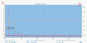
Some weeks ago a customer of my SW and I experimented (also some years back) on that harmonic cancellation already 😀
My Sine & Harmonic generator was used with various try and error settings.
Conclusion:
1. this works 😎
2. All harmonic settings (level & phase) are level dependent

3. The levels where about -110dB to... -120dB
4. the phase really made the beef
in other words, it's not clear where all influences comes from: DAC SDM algorithm, DAC circuit, output buffer and each interactions...
see attached picture... with 2. Harmonic removed
Cheers
Hp
Attachments
You are suggesting that a DAC could have "pre-distorted" data that would remove any intrinsic distortion? The next question would be can that be applied to any audio? Probably figuring the predistortion may make the process really compute intensive.
It's easy to propose several very tedious processes to do this. I wonder though at what level the stationarity of the DAC comes into play. I've always wanted to try my idea of one DAC channel with a second at 1/256 full scale as a correction injector. That way you should be able to get results only using 16 bits like the Octave interface in the last LA. Also I would expect modern DAC's to be very stable with time and temp. at 16 bits.
Last edited:
I think one could make that work for simple stationary signals like single or
even two or three sines or triangles. That could even be tuned automatically
under processor control. Maybe a lot of work, but not complicated.
For arbitrary signals, I would not dare to bet. You then have to include
the effects of the history, and that might be different for each single
conversion.
or triangles.
I wouldn't start with high levels of harmonics in the source, DAC's doing -100dB sines are pretty standard. It's just asking for more confounders.
gerhard - You should ask Samuel about the de-glitcher needed to get ADI's newish multi-bit 20 bit DAC to do audio, quite heroic. Reminds me of the days of a failed effort to do a Kelvin - Varley DAC + de-glitcher as the next thing for audio.
Last edited:
- Home
- Design & Build
- Equipment & Tools
- Low-distortion Audio-range Oscillator