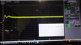
David --- i think this is my issue..... scanning the 500+ page Audio Precision manual is this weird little jem on page 493 !!
😱
View attachment 594167
I am comparing results with 3 other analyzer brands at this time whose monitor outputs ARE calibrated and useful for further analysis. .
THx-RNMarsh
Richard this is system specific stuff. I'm thinking we should either start another thread or go to email on this.
You can calibrate the monitor output to the sound card or other reading device. This eliminates the error unless there is a BW restriction.
Last edited:
That's one of the things I like so much on my dScope*. Calibrated low noise monitor outputs, selectable outputs (bandpass, residual, etc) and selectable gain from 0dB to 60dB! Great for further processing of the residual.
*The other thing is the ability to have time domain and frequency domain curves in the same graph but with independent scaling. These guys obviously use their own equipment for audio design 😉
Jan
*The other thing is the ability to have time domain and frequency domain curves in the same graph but with independent scaling. These guys obviously use their own equipment for audio design 😉
Jan
Hi Richard
Your reading of the "Monitor Outputs" is correct. AP System One, Two, Cascade & 2700 monitor outputs are not calibrated as the final signal path to the A2D is the CALIBRATED PATH. The BW is good however the levels will vary slightly.
Duke
Your reading of the "Monitor Outputs" is correct. AP System One, Two, Cascade & 2700 monitor outputs are not calibrated as the final signal path to the A2D is the CALIBRATED PATH. The BW is good however the levels will vary slightly.
Duke
Maybe you can calibrate them? Add a known signal to the source and check it with the 725 for validation. Then see how odd the monitor output of the AP actually is. Do you have a service manual? Or at least a block diagram showing how the signals are routed and processed? For this the extra signal doesn't need to be phase locked or anything like that.
What I do with the Shibasoku 725 and the emu0204 is, in level mode on the 0dBV range apply a 1kHz 1Vrms signal to the 725 input. Then adjust the input gain on the emu0204 until the FFT agrees. This assumes the emu0204 and software has already been cal'd.
It's tricky with QA400 because there is no input gain adjustment. But you can use the extra gain function to scale the software.
You can also use any line type amplifier which has a gain setting to calibrate the read out device. It's impossible at this point in the signal chain to add any significant distortion and noise will have little effect. So the amplifier doesn't have to be anything special provided it has the BW.
Last edited:
Last edited:
If the reinjection is calibrated it tells you what the harmonic level and phase was. A dsp wizard could possibly build an app that figures out the distortion components this way by individually cancelling each building a data set in the process.
Sent from my LG-H811 using Tapatalk
Sent from my LG-H811 using Tapatalk
If the reinjection is calibrated it tells you what the harmonic level and phase was. A dsp wizard could possibly build an app that figures out the distortion components this way by individually cancelling each building a data set in the process.
Sent from my LG-H811 using Tapatalk
Actually that is my technique for building a low distortion oscillator.
I thought I had mentioned it. You start with a variable frequency master oscillator. The fundamental should be a fraction of that. Then you can use the master clock to drive lock-in amplifiers on the harmonics. Up to about the fifth. That allows the adjustment of phase and amplitude of the correction oscillators.
As you can check the distortion after the level control you can get quite good results. The other issue in your favor is that the distortion correction signals only need be moderately low distortion as they not only are attenuated by at least 80 dB, the 2nd order one wil also get some correction from the higher order ones. Same for all but the highest order one.
Neat thing is the lock-in amplifier only needs to sample harmonics after a change.
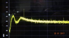
with a phase lock on the source fundamental freq, one can phase shift the buffered freq enough to re-inject into fund and cancel harmonics. Just a quick proof of concept shows atten the 3H pushed below -150dB. Will do 2H next.....
View attachment 594598
THx-RNMarsh
Very interesting.
If the reinjection is calibrated it tells you what the harmonic level and phase was. A dsp wizard could possibly build an app that figures out the distortion components this way by individually cancelling each building a data set in the process.
Sent from my LG-H811 using Tapatalk
I was considering this for my next gen project.
I just suggested to Richard in a email to try using an IC multiplier to generate a sync'd second harmonic. If the low pass and band pass output of the gen are used as source to the multiplier inputs x and Y there will be no DC component on the multiplier output. It's then possible to direct couple to the gen input.
If the gen band pass output is inverted and looped back to the gen input this increases the damping to the oscillator which is normally done by the control multiplier. If the right amount of signal is injected it forces the multiplier to shut down. This eliminates both the noise and distortion contribution of the multiplier. The effect is manual replacement. But the noise and distortion of the loop components are added. Which are probably lower.
Additionally, if manual damping exceeds what the control applies the additional damping will cause the gen level to drop. If the level drops then the distortion reduction is from the gen operating at a lower level. It's important to keep an eye on the gen output level before coming to a conclusion.
Additionally, if manual damping exceeds what the control applies the additional damping will cause the gen level to drop. If the level drops then the distortion reduction is from the gen operating at a lower level. It's important to keep an eye on the gen output level before coming to a conclusion.
Last edited:
Actually that is my technique for building a low distortion oscillator.
I thought I had mentioned it. You start with a variable frequency master oscillator. The fundamental should be a fraction of that. Then you can use the master clock to drive lock-in amplifiers on the harmonics. Up to about the fifth. That allows the adjustment of phase and amplitude of the correction oscillators.
As you can check the distortion after the level control you can get quite good results. The other issue in your favor is that the distortion correction signals only need be moderately low distortion as they not only are attenuated by at least 80 dB, the 2nd order one wil also get some correction from the higher order ones. Same for all but the highest order one.
Neat thing is the lock-in amplifier only needs to sample harmonics after a change.
It may be far simpler to start with a good digital source and DAC and then a tuneable active or passive filter on the output (state variable?). Even with passive components and relays it would not be much more complex plus the potential of much lower distortion. The best DAC's start with harmonics at -130 or so http://www.diyaudio.com/forums/equi...zer-ak5397-ak5394a-ak4490-78.html#post4963557 so a simple filter would get between 6 and 30 db additional reduction. A well done filter significantly more.
how low could you go digitally?
just build a composite summing amp, connect up 8 channel pro ADC/DAC like Motu 8A with ESS chips
then sw could auto cal by using 7 of the channels at -1/7 signal to null the remaining DAC channel operating at +1 sine output
assuming that the 7 outputs working at 1/7 amplitude have 1/7**n less nth order distortion...
rinse, repeat for each DAC channel in turn, possibly add downward bootstrapping or try to identify nonlinear models
Let me check what I have at home this weekend, as well as your postal address.
Patrick
Viktor,
I have both 10nF & 22nF 16V 2%.
How many would you need ?
Please kindly send me your address again by PM, just to be sure.
Patrick
Viktor,
I have both 10nF & 22nF 16V 2%.
How many would you need ?
Please kindly send me your address again by PM, just to be sure.
Patrick
Probably more than one, but not so many. Maybe five examples from the each value. The performance is unknown, and may be variable within different examples from the one value. I'll send you PM.
Victor.
I have long advocated distortion cancellation in audio amps. When we have super low harmonics and want to have NO harmonics... cancellation needs to be tried.
The gen is ultra low distortion. With some very simple non-optimum cancellation tests , I have 2H = -140dB and 3H = -150dB. Now, we will all think of the cancellation or filtered out of remaining very low residue.
Several approaches have been suggested but not tried.
Well......... ?

THx-RNMarsh
The gen is ultra low distortion. With some very simple non-optimum cancellation tests , I have 2H = -140dB and 3H = -150dB. Now, we will all think of the cancellation or filtered out of remaining very low residue.
Several approaches have been suggested but not tried.
Well......... ?

THx-RNMarsh
For ultra pure sine sources I think analog frequency domain processing wll be the ultimate answer. noise is an issue as is frequency stability (something a divided crystal oscillator has over any analog oscillator) and a passive low pass filter should have less harmonics and other stuff than any other method. This would be for below -150 especially. Even passive summing networks will bring problems.
However tuned harmonic addition is a really interesting way to measure distortion.
However tuned harmonic addition is a really interesting way to measure distortion.
For ultra pure sine sources I think analog frequency domain processing wll be the ultimate answer. noise is an issue as is frequency stability (something a divided crystal oscillator has over any analog oscillator) and a passive low pass filter should have less harmonics and other stuff than any other method. This would be for below -150 especially. Even passive summing networks will bring problems.
However tuned harmonic addition is a really interesting way to measure distortion.
The tuning stability was next on the list for additions to the dlbSVO. That is locked to a crystal.
But can't seem to find much on this for the audio range.
It is possible to do a really good frequency counter and lock it that.
- Home
- Design & Build
- Equipment & Tools
- Low-distortion Audio-range Oscillator
