Hi Pete,
Thanks for that manual. I looked at the specs on distortion residual and it looks like it is spec'd at -80dB (0.01%) if I interpreted that correctly. Unless it does much, much better than spec'd, it is not that impressive. But the automation is nice. Looks like it came out in the late '90s.
An SV notch may not typically be as good as an active twin-T. First, it has several more op amps; second, it probably almost always needs to be auto-tuned, so you have the same type of distortions introduced as in an audio oscillator, those including distortion of the (JFET) agc element and distortion introduced by the agc level-detect/control circuit.
Cheers,
Bob
The more advanced linear tech notes by Jim Williams suggest a Cds photocell, have you considered that for an SV oscillator? Also used here in this .pdf:
http://www.janascard.cz/PDF/An ultra low distortion oscillator with THD below -140 dB.pdf
Hi Pete,
Thanks for that manual. I looked at the specs on distortion residual and it looks like it is spec'd at -80dB (0.01%) if I interpreted that correctly. Unless it does much, much better than spec'd, it is not that impressive. But the automation is nice. Looks like it came out in the late '90s.
An SV notch may not typically be as good as an active twin-T. First, it has several more op amps; second, it probably almost always needs to be auto-tuned, so you have the same type of distortions introduced as in an audio oscillator, those including distortion of the (JFET) agc element and distortion introduced by the agc level-detect/control circuit.
Cheers,
Bob
I think the specs are written so that they have a lot of wiggle room. All of them I have checked were significantly better that -80 dB.
The Boontons when carefully adjusted stock can get below -100 dB THD+N. With the mods they are more stable. The Boonton is sort of based on the HP8903. The SV notch sees to work quite well. The limitation seems to be the analog multipliers. I hope to try a newer multiplier if I can figure out how to patch it in.
The SVO uses two multipliers. One for gain and one for frequency. In both its really accurate. I have measured less than .01 dB across most of the range and the frequency is crystal stabilized with 5 digits of resolution. The FET attenuator may limit the distortion (don't know yet) and the output amp may need some help as well. However having a 50 Ohm source good for 14V can be really nice. The other nice trick is that the source is completely floating with no connection to ground.
The more advanced linear tech notes by Jim Williams suggest a Cds photocell, have you considered that for an SV oscillator? Also used here in this .pdf:
http://www.janascard.cz/PDF/An ultra low distortion oscillator with THD below -140 dB.pdf
I've never used a Cds photocell for this purpose; interesting possibility. I suppose it is possible that it might be lower distortion than a properly-designed JFET.
Cheers,
Bob
I've never used a Cds photocell for this purpose; interesting possibility. I suppose it is possible that it might be lower distortion than a properly-designed JFET.
Cheers,
Bob
I've experimented with it, and for me it didn't really add anything useful. You still have the ripple on the control side, and the relative slow response, while attenuating the effect of control-signal ripple for higher frequencies, doesn't make control loop dynamics any easier.
Jan
The Sound Technology ST1700 oscillator is one of the best examples of a photocell stabilized oscillator. It uses a Jfet for fast settling and switches to the photocell after a delay whenever the frequency is changed. John Curl managed to get the distortion well below -100 dB with opamp upgrades etc.
The best photo cell implementation would use an incandescent bulb which is sort of a true RMS detector and down to a pretty low frequency will be pretty ripple free. The cells themselves are also slow to respond further removing ripple.
There is a new source for them that is supposed to be lower distortion. They have a high voltage coefficient so keeping the voltage across the cell low is critical for best performance.
Attachments

david's generator looks very good on first pass on the AP2722. -137dBV for 2H and 3H. You can take away some DB's as the ref is higher than 1v standard.
I'll go to the monitor output and run it thru the QA401, next.
There is some instability in the gen but I'll sort that out with David Could just be operator error.

THx-RNMarsh
I'll go to the monitor output and run it thru the QA401, next.
There is some instability in the gen but I'll sort that out with David Could just be operator error.
THx-RNMarsh
Last edited:
david's generator looks very good on first pass on the AP2722. -137dBV for 2H and 3H. You can take away some DB's as the ref is higher than 1v standard.
I'll go to the monitor output and run it thru the QA401, next.
There is some instability in the gen but I'll sort that out with David Could just be operator error.
View attachment 593488
THx-RNMarsh
Richard the SVO app is showing 0Hz for frequency on the frequency counter readout.
The micro controller can't operate this way. It must have a frequency pulse from the main board.
I suspect the shielded cable connected from the SVO main board to the micro controller board has come loose in shipping or it's broken. It is this signal that tells the micro controller the SVO main board has power. The micro controller initializes at power up when the frequency of the SVO is measured greater than 0Hz. Without this signal the SPI port expander on the SVO board may not be initialized or at least not properly
Therefore "some instability" is an understatement.
Slide the lid off and make sure the connectors are seated properly on both boards.
Last edited:
You are looking at input channel "B". see channel input "A". 2.45v/1KHz on the left side of screen.
THx-RNMarsh
THx-RNMarsh
You are looking at input channel "B". see channel input "A". 2.45v/1KHz on the left side of screen.
THx-RNMarsh
I'm not looking at the AP.
The SVO app clearly shows 0Hz. Bottom right of pic.
That means the mentioned cable is unplugged.
Richard check your email.
Let's discuss this off the forum.
Last edited:
Ok I will check..... thee gen produces output even though the app says there is no freq (0 Hz).
Meanwhile, can we get 3v output or 1v output rather than 2.5v ?
2.5v is 8dB hot from the analyzers normal ref input level. 3v would allow a nice 10dB figure to use in calc.
As shown via the 725D analyzer, it's monitor output going to a QA401 FFT --->

You can add 8dB to these numbers to get the actual harmonic level refered to the input level of 2.5v.
THx-RNMarsh
Meanwhile, can we get 3v output or 1v output rather than 2.5v ?
2.5v is 8dB hot from the analyzers normal ref input level. 3v would allow a nice 10dB figure to use in calc.
As shown via the 725D analyzer, it's monitor output going to a QA401 FFT --->
You can add 8dB to these numbers to get the actual harmonic level refered to the input level of 2.5v.
THx-RNMarsh
Last edited:
UPdate -- there was another connector which was loose, intermittent. With David's intimate knowledge he directed me right to the likely problem. Re seated, all works great.
There was no instability due to the circuit design or operation. Just a couple connectors got dislodged during shipping.
Thx-Richard
There was no instability due to the circuit design or operation. Just a couple connectors got dislodged during shipping.
Thx-Richard
Ok I will check..... thee gen produces output even though the app says there is no freq (0 Hz).
Meanwhile, can we get 3v output or 1v output rather than 2.5v ?
2.5v is 8dB hot from the analyzers normal ref input level. 3v would allow a nice 10dB figure to use in calc.
As shown via the 725D analyzer, it's monitor output going to a QA401 FFT --->
View attachment 593561
You can add 8dB to these numbers to get the actual harmonic level refered to the input level of 2.5v.
THx-RNMarsh
Can it go to 1Vrms. Absolutely not. The SNR would be poor all you'd be looking at is noise. It best to start high then attenuate. Can it be set for 3Vrms. In short yes but not an easy procedure. It requires some expertice understanding of the design and know how on how to set everything. The operating level is part of the loop gain and the limiting circuit would also need to be adjusted. The distortion will rise setting the level higher. The 2.5Vrms is optimal for this gen. It's set for best SNR and distortion performance. Each is a trade off.
What is needed is a post amplifier and attenuator. I haven't found an amplifier yet which is transparent to the distortion of the generator. But I will.
What you have there is a source.
What range is the 725D set to? The measurement shown doesn't make any sense.
What you are showing is way too high and it is not clean as it is in my posts.
You need to be connected to the LP (Low Pass) output of the generator. It looks like your are connected to the BP output. 6dB less slope attenuation.
Last edited:
yes it was BP output. I dont see any thd change between the two. I'll check again. The 725 was set on the 3v range (+10dB). This makes the monitor output zero reference line at -110dB from gen source level (technically +8).
BTW - i tried to put a 150K in series with the 100K 725D input... gets me to 1v and using the 1v scale on the 725. But seems the 725 doesnt like high Z inputs sources.
So a buffer and control as you have been looking for is needed sometimes. Esp to test other DUT with.
I get pretty much the same distortion on three analyzers... panasonic, shibasoku and AP. small differences mostly with the 2H) only. It has bothered me that others, besides yorself, get much lower readings with their various sources.
THx-RNMarsh
Last edited:
yes it was BP output. I dont see any thd change between the two. I'll check again. The 725 was set on the 3v range (+10dB). This makes the monitor output zero reference line at -110dB from gen source level (technically +8).
BTW - i tried to put a 150K in series with the 100K 725D input... gets me to 1v and using the 1v scale on the 725. But seems the 725 doesnt like high Z inputs sources.
So a buffer and control as you have been looking for is needed sometimes. Esp to test other DUT with.
I get pretty much the same distortion on three analyzers... panasonic, shibasoku and AP. small differences mostly with the 2H) only. It has bothered me that others, besides yorself, get much lower readings with their various sources.
THx-RNMarsh
If you put a resistor in series with the 725D you will raise the noise to a level the 725D can't deal with.
If you can't measure a difference between the BP and LP output then you at your analyzer residual. That's as low as you can measure.
I can't measure the generator through it's entire range on Shibasoku 725C. I have to use the 725D. The 725C residual is too high and this limit the distortion measurement.
But this 725D has been hot rod.
So has the 725C but the harmonics of the notch filters limits the measurement.
However both the 725C and 725D show better results.
The input level might matter for AP2722 but 2.5Vrms certainly does not for the Shibasoku 725C or D. I think Demian said that 3Vrms is optimal for the Shibasoku.
When I repeated measurements using the QA400 for readout of the monitor output there was no difference from the EMU0204. But the whole system must be calibrated first.
In level mode if you input 1Vrms to the 725D in the 1Vrms range your meter should indicate FS (10). The monitor output is the same 1Vrms at FS. The QA FFT must read the same FS 1Vrms (0dBV). Then do your distortion measurement on the 725D.
Please specify the distortion measurement range i.e. 90dB, 100dBV 110dBV etc. with you measurement posts.
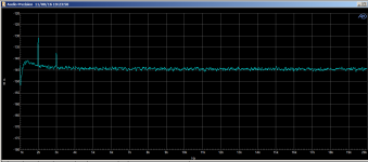
Yes, this is normal procedure. In your case, with 2.5v, I use the 3volt range on the 725D instead of the one volt range. I said this in last note above. The range is the lowest -100dB fs when in analyze mode... as you would expect for a source gen of this ultra low thd.
With this info, I get the 2H at -140 and 3H at -146dB. Is that how you read it also? What levels do you have for 2H and 3H?
The biggest issue when testing at these levels is still ground leakage and noise etc. But, as you can see, it is fairly free from extraneous freqs.
THx-RNMarsh
.
Last edited:
Yes, this is normal procedure. In your case, with 2.5v, I use the 3volt range on the 725D instead of the one volt range. I said this in last note above. The range is the lowest -100dB fs when in analyze mode... as you would expect for a source gen of this ultra low thd.
With this info, I get the 2H at -140 and 3H at -146dB. Is that how you read it also? What levels do you have for 2H and 3H?
The biggest issue when testing at these levels is still ground leakage and noise etc. But, as you can see, it is fairly free from extraneous freqs.
THx-RNMarsh
.
These are correct harmonic levels for 1kHz. Try 2kHz. Might be much better.
However the gen might still be lower if this is the residual of the analyzer(s).
I haven't verify this yet.
It requires a passive notch filter but the Shibasoku 725 can't operate on a suppressed fundamental level. That leaves a sound card or other ADC device.
Dimitri has done some work in this regard on the AP2722.
Perhaps Dimitri can comment.
Ok I will check..... thee gen produces output even though the app says there is no freq (0 Hz).
Meanwhile, can we get 3v output or 1v output rather than 2.5v ?
2.5v is 8dB hot from the analyzers normal ref input level. 3v would allow a nice 10dB figure to use in calc.
As shown via the 725D analyzer, it's monitor output going to a QA401 FFT --->
View attachment 593561
You can add 8dB to these numbers to get the actual harmonic level refered to the input level of 2.5v.
THx-RNMarsh
Richard the Shibasoku automatically scales the input level. The nominal output from the input amplifier is 5Vrms no what you put in. If the everything is setup right and the analyzer is in the 100dBV range you should be able to do a direct read on the FFT assuming a FS of 0dBV. No need to do more than subtract 100dBV from the QA reading.
Why are we considering 8dB for the 2.5Vrms input. All my measurements are direct with the 725.
All your analyzers are automatic and should be doing the same for the monitor output if there is one. Not sure about the AP2722. never used one.
There is a difference between how this amplifier works between level mode and analyzer mode. It's not the same.
Last edited:

- Home
- Design & Build
- Equipment & Tools
- Low-distortion Audio-range Oscillator