Dick,
Very clever idea. I would stand the circuit off a bit more than needed because in theory the lowest noise would be with it centered.
I also take it you got your AC fixed!
ES
Very clever idea. I would stand the circuit off a bit more than needed because in theory the lowest noise would be with it centered.
I also take it you got your AC fixed!
ES
HaHaHa. I think it might catch on... one issued with each FFT system. Available everywhere and cheap enough. Paint it to match the room colors. Tie a ribbon on the lid handle.
All the tests I did were only as proof in that each one was like a Go-No_Go test for the direction to proceed in finding the source(s). They are quick experiments. Now, I fully expect to have a final product with a steel shell. About an inch seperation from any circuity will be fine. Insulated stand-offs? A box within a box.
THx-RNMarsh
Double shielding.
Double shielding.
yes, what I called a box within a box.
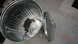
Here is the outer "box" - with the inner box inside --> both the inner shielded box and the outer shielded box are grounded thru separate wires to the input of the A-P. The grounding of the inner box shield is from the coax shield common. The other is a wire going from the outer box (can) to input of the A-P.
THx-RNMarsh
Attachments
Double shielding.
yes, but one must be made of steel for low freq EMI shielding.
-RM
🙂 I got my a/c fixed.... motor start cap was all. I had a spare in the garage. BTW-- dont let anyone put a made in China cap there... will last about a year only. I got a GE unit... the 60,000 hour type. That should take care of that type problem for long time.
-RM
-RM
What failure mode did your capacitor show? I encountered a made-in-China motor cap with capacitance about 40% lower than the rated value. Was your problem like mine?🙂 I got my a/c fixed.... motor start cap was all . . . .
Almost 3 yrs ago I replaced the failed blower motor in my HVAC unit. Grainger had an exact-replacement motor for around $200, and a generic motor for about $100. I took the cheap motor, and when the counterman suggested I needed a start cap I bought it. As I recall, it was a 5 uF/240 VAC polypropylene cap. (Actually, it's a RUN capacitor on a permanent split capacitor motor but "start capacitor" seems to be the common nomenclature in the HVAC service industry.)
Well, from the start that generic motor groaned and grumbled for several seconds at every startup. I checked the mounting brackets for binding and proper alignment, looked for an unbalanced or out-of-round squirrel cage, measured resistance of the wiring and relay contacts, but couldn't find any cause for the hard-start problem. Last fall, after 2 years, the blower motor occasionally wouldn't start at all - it buzzed and groaned until the thermal cutout operated, then usually started after the thermal cutout reset itself. In a day or so the failure-to-start was happening every 4th or 5th attempt. This time I DID find a damaged squirrel cage and replaced it.
But even with the new, well-balanced, squirrel cage the motor occasionally failed to start. I was resigned to going back for the "exact replacement" motor, but it was the weekend so I decided to try a stop-gap repair. I wired an additional capacitor in parallel with the run capacitor. The motor's specified capacitor was 5 uF/240 VAC. The one I added in parallel was 10 uF/440 VAC and physically VERY MUCH larger. Due to space restrictions I had to "mount" it with duct tape on the outside of the blower cabinet.
With the two capacitors, the motor started and ran just fine - no groaning. With just the 10 uF capacitor, performance was equally good. I would have been content to permanently install the 10 uF, but there was no place to put it. On a whim, I measured the capacitance of the "correct" capacitor. Surprise! The "5 uF" capacitor measured only about 3 uF! I had never seen a film cap fail with low capacitance, so I got a second multimeter and verified the results.
I then drove 20 miles, arriving at Branneky Hardware (the only surviving "real" hardware store on my side of St Louis) about 5 minutes before closing on Saturday evening. The counterman didn't know whether to be amused or aggravated when I pulled out the multimeter to see if the capacitor he wanted to sell me was within tolerance. It was. With that replacement cap in place, the blower motor has reliably started without any groaning and rumbling ever since.
I have been in electronics for over half a century, and have seen quite a few failed capacitors. I have seen film capacitors fail open or short, but never with low capacitance. (Electrolytics are another story.) I suspect Grainger's "5 uF" cap was significantly less than 5 uF from the day I bought it - the blower motor never started smoothly. I don't know whether the capacitance declined further over time, or whether wear-and-tear on the replacement motor required more starting current. It never occurred to me to check the capacitance of a brand-new capacitor. Like you, I'm now suspicious of "Made in China" motor capacitors but don't know where I can easily purchase any other kind!
Dale
I see some confusion on how shielding works here. It is actually a common problem and one of the reasons the EMI courses are popular even if expensive. I'm sure there are many watchers who would appreciate a quick introduction.
Magnetic shielding works differently from electrostatic shielding. With a magnetic field the goal is to provide a path around the shielded circuit that will shunt the external field so it doesn't pass through your device. John Curl's SOTA "piglet" preamp is a excellent example of simple implementation. It was a steel tube maybe 1/8" thick that the circuit was inside of. The steel was thick enough and magnetically soft enough that pretty much all the external field would concentrate in the steel and none would be inside. The core principle is that the magnetic shield is a pretty complete housing and with generous overlapping of seams. Welded seams can degrade the magnetic properties enough to degrade the shielding. If its magnetized the available flux before saturation gets used up and then it becomes transparent to the external field. Similar to a saturated cored inductor: the inductance drops to that which the coil would have without the core.
An electrostatic shield is used to create a constant electrostatic potential around the circuit at a known fixed potential to the internal circuit. it needs to be a conductive bubble around the circuit. Holes allow the external potential to affect what is inside. At RF the wavelengths matter as to the size of the holes. Long seams that are not electrically connected with an emi gasket can let in RF and are even used as antennas in some cases.
For this project a cake tin (steel) if big enough may work quite well. The walls will be thick enough to shunt a smaller field and have enough overlap to be continuous.
A sheet of steel will do very little since the wavelengths are long and will easily wrap around a panel. The RF absorber can help reduce RF radiation close to a source but won't do much for audio frequency radiation.
I could not find any quick intros but here are some background readings:
http://www.analog.com/static/imported-files/tutorials/MT-095.pdf
EMC EMI RFI ESD | EDN
LearnEMC: Shielding Theory
Hi Demian,
Thanks for this excellent explanation.
I do have a couple of questions that may reflect some of my incomplete knowledge here. With regard to shielding from ac magnetic fields for electronic devices, I always tended to think that the main function of the shield was to form a highly conductive electrical shunt of the ac magnetic field, as with a "shorted turn". This function would be served by an aluminum or copper enclosure. When I see a device in a very substantial aluminum enclosure, that is what comes to mind (of course, such an enclosure surely also serves the purpose of electrostatic shielding).
Also, further to the concept of the shorted turn shunt, aluminum and copper are far better conductors than steel. Of course, there are also those who prefer high-end audiophile circuits to not be in proximity to ferrous materials.
I do like your comment about the possibility of magnetic saturation of the shield. However, it would seem that the ac magnetic field against which we are shielding would be far too weak to get close to saturating the shield material.
I also agree completely with your point about the electrostatic field surrounding the electronics. However, I have had really good success when I have put a large conductive, grounded sheet under the circuit I am working on. A large piece of un-etched single-sided PWB material works pretty well. It is easy to solder a grounding wire to it.
Cheers,
Bob
good conductors like Al, Cu only shield AC mag field by means of the induced eddy currents opposing, "reflecting" the incident mag field component
for this to be effective the conductive shielding has to be multiple times the skin depth in thickness at the frequency of the AC mag field
Al skin depth at 60 Hz is 0.43" - varies with the conductivity of the alloy- so well over an inch thick Al is required to be useful at 60 Hz
lining a steel box with Al foil has little effect below MHz
Hi Demian,
Thanks for this excellent explanation.
I do have a couple of questions that may reflect some of my incomplete knowledge here. With regard to shielding from ac magnetic fields for electronic devices, I always tended to think that the main function of the shield was to form a highly conductive electrical shunt of the ac magnetic field, as with a "shorted turn". This function would be served by an aluminum or copper enclosure. When I see a device in a very substantial aluminum enclosure, that is what comes to mind (of course, such an enclosure surely also serves the purpose of electrostatic shielding).
Also, further to the concept of the shorted turn shunt, aluminum and copper are far better conductors than steel. Of course, there are also those who prefer high-end audiophile circuits to not be in proximity to ferrous materials.
I do like your comment about the possibility of magnetic saturation of the shield. However, it would seem that the ac magnetic field against which we are shielding would be far too weak to get close to saturating the shield material.
I also agree completely with your point about the electrostatic field surrounding the electronics. However, I have had really good success when I have put a large conductive, grounded sheet under the circuit I am working on. A large piece of un-etched single-sided PWB material works pretty well. It is easy to solder a grounding wire to it.
Cheers,
Bob
Hi Bob,I do the same with the grounded FR4. I also place a transparent sheet over the top and grounded aluminum foil on over that. Works quite well. The plastic and aluminum is easy to remove if I need to do something.
jcx;3991089 lining a steel box with Al foil has little effect below MHz[/QUOTE said:It has the effect of reducing the hysteresis induced distortion of the steel case on the circuitry's conductors. Dick just used a larger case to avoid the problem.
But I am glad you mentioned that non ferrous metals also provide shielding.
good conductors like Al, Cu only shield AC mag field by means of the induced eddy currents opposing, "reflecting" the incident mag field component
for this to be effective the conductive shielding has to be multiple times the skin depth in thickness at the frequency of the AC mag field
Al skin depth at 60 Hz is 0.43" - varies with the conductivity of the alloy- so well over an inch thick Al is required to be useful at 60 Hz
lining a steel box with Al foil has little effect below MHz
😎🙂
Copper and aluminum are almost Completely ineffective at 60hz.... at least when compared to steel.
-RM
What failure mode did your capacitor show? I encountered a made-in-China motor cap with capacitance about 40% lower than the rated value. Was your problem like mine?
Almost 3 yrs ago I replaced the failed blower motor in my HVAC unit. Grainger had an exact-replacement motor for around $200, and a generic motor for about $100. I took the cheap motor, and when the counterman suggested I needed a start cap I bought it. As I recall, it was a 5 uF/240 VAC polypropylene cap. (Actually, it's a RUN capacitor on a permanent split capacitor motor but "start capacitor" seems to be the common nomenclature in the HVAC service industry.)
Well, from the start that generic motor groaned and grumbled for several seconds at every startup. I checked the mounting brackets for binding and proper alignment, looked for an unbalanced or out-of-round squirrel cage, measured resistance of the wiring and relay contacts, but couldn't find any cause for the hard-start problem. Last fall, after 2 years, the blower motor occasionally wouldn't start at all - it buzzed and groaned until the thermal cutout operated, then usually started after the thermal cutout reset itself. In a day or so the failure-to-start was happening every 4th or 5th attempt. This time I DID find a damaged squirrel cage and replaced it.
But even with the new, well-balanced, squirrel cage the motor occasionally failed to start. I was resigned to going back for the "exact replacement" motor, but it was the weekend so I decided to try a stop-gap repair. I wired an additional capacitor in parallel with the run capacitor. The motor's specified capacitor was 5 uF/240 VAC. The one I added in parallel was 10 uF/440 VAC and physically VERY MUCH larger. Due to space restrictions I had to "mount" it with duct tape on the outside of the blower cabinet.
With the two capacitors, the motor started and ran just fine - no groaning. With just the 10 uF capacitor, performance was equally good. I would have been content to permanently install the 10 uF, but there was no place to put it. On a whim, I measured the capacitance of the "correct" capacitor. Surprise! The "5 uF" capacitor measured only about 3 uF! I had never seen a film cap fail with low capacitance, so I got a second multimeter and verified the results.
I then drove 20 miles, arriving at Branneky Hardware (the only surviving "real" hardware store on my side of St Louis) about 5 minutes before closing on Saturday evening. The counterman didn't know whether to be amused or aggravated when I pulled out the multimeter to see if the capacitor he wanted to sell me was within tolerance. It was. With that replacement cap in place, the blower motor has reliably started without any groaning and rumbling ever since.
I have been in electronics for over half a century, and have seen quite a few failed capacitors. I have seen film capacitors fail open or short, but never with low capacitance. (Electrolytics are another story.) I suspect Grainger's "5 uF" cap was significantly less than 5 uF from the day I bought it - the blower motor never started smoothly. I don't know whether the capacitance declined further over time, or whether wear-and-tear on the replacement motor required more starting current. It never occurred to me to check the capacitance of a brand-new capacitor. Like you, I'm now suspicious of "Made in China" motor capacitors but don't know where I can easily purchase any other kind!
Dale
Several things are at work here. The cap must have the UL label on it or no standard is being adhered to. In such cases, the film is too thin and the voltage rating is fudged/marginal. If the film is metallized (cheaper and smaller size) then the metal can get burned off when arcing internal happens... results in less plate material -- thus lower capacitance. Over time, the c just isnt enough anymore. Also, the cap should be mounted to metal to act as heat sink.
-RM
I was just thinking out loud.What effect would a static magnetic field have on an alternating magnetic field?
Easy to try.
I was thinking that saturating the magnetic field with a DC magnetic field might help.
It measured -146dB
Now that the EMI/RFI is cleared up from the measurement system.......
Here is the true (according to A-P 2722) level of harmonics of a 1KHz signal from the osc/generator that David has designed;
David.... YOU designed this. You did the study and figured the best way and did the hard work. Yes, many here at DIY contributed input and help in various ways. That doesnt make it part their design... help is help. It is your design/work and you went thru all the permutations and sorted out what would be the best way. A 2 year effort deserves a big round of applause. Now here 's the fruit of your labor:


THx and I really mean THX, Richard Marsh
Now that the EMI/RFI is cleared up from the measurement system.......
Here is the true (according to A-P 2722) level of harmonics of a 1KHz signal from the osc/generator that David has designed;
David.... YOU designed this. You did the study and figured the best way and did the hard work. Yes, many here at DIY contributed input and help in various ways. That doesnt make it part their design... help is help. It is your design/work and you went thru all the permutations and sorted out what would be the best way. A 2 year effort deserves a big round of applause. Now here 's the fruit of your labor:
THx and I really mean THX, Richard Marsh
Last edited:
I think I am going to put a couple isolated BNC and three binding posts on this Can shield. And, a ground post to the can. And keep it.
I can always carry junk in it when not being used as an EMI shield. 🙂
-Richard
I can always carry junk in it when not being used as an EMI shield. 🙂
-Richard
Last edited:
In looking at higher and lower freqs --- The highest distortion is at 10Hz... 2H about -120 and 3h about -130. At higher freqs the level is about -140 to -145db range for 2h and 3H.
I didnt normallize the level to 1.0v as I would have to go thru a pot (potential for distortion and more hum pickup). But you might drop these numbers at least 6dB if we are measuring at 1v input level.
That 10Khz 'harmonic' at -145dB doesnt seem to be a harmonic of the gen... it is there at any freq..... maybe a clock running inside the osc/gen?
I'll check again the higher freqs for distortion above 10KHz soon. maybe tonight.
THx-RNMarsh
In looking at higher and lower freqs --- The highest distortion is at 10Hz... 2H about -120 and 3h about -130. At higher freqs the level is about -140 to -145db range for 2h and 3H.
I didnt normallize the level to 1.0v as I would have to go thru a pot (potential for distortion and more hum pickup). But you might drop these numbers at least 6dB if we are measuring at 1v input level.
That 10Khz 'harmonic' at -145dB doesnt seem to be a harmonic of the gen... it is there at any freq..... maybe a clock running inside the osc/gen?
I'll check again the higher freqs for distortion above 10KHz soon. maybe tonight.
THx-RNMarsh
I don't know if this is relevant or not but it looks like you have the AP's generator set to 10Khz.
In looking at higher and lower freqs --- The highest distortion is at 10Hz... 2H about -120 and 3h about -130. At higher freqs the level is about -140 to -145db range for 2h and 3H.
I didnt normallize the level to 1.0v as I would have to go thru a pot (potential for distortion and more hum pickup). But you might drop these numbers at least 6dB if we are measuring at 1v input level.
That 10Khz 'harmonic' at -145dB doesnt seem to be a harmonic of the gen... it is there at any freq..... maybe a clock running inside the osc/gen?
I'll check again the higher freqs for distortion above 10KHz soon. maybe tonight.
THx-RNMarsh
The internal oscillator is set at 10K from your screen shot, that is what is showing in the FFT. It is crosstalk inside the AP. Not from the oscillator. Yes the panel says the output is off, that doesn't mean the oscillator is off.
Richard, are you measuring David's oscillator distortion or AD797 based AP front end distortion?

- Home
- Design & Build
- Equipment & Tools
- Low-distortion Audio-range Oscillator