3 hours before
"I changed the 45B Rk to 1250ohms. This gives:
Ua = 416.5V
bias = 67V
52.5 mA
Ua - bias = 349V"
--------------------------
Now
"Left mono-block
C2 B+ 430, Ua 420, Rk 1250, bias 66.2
Right mono-block
C2 B+ 431, Ua 419.6, Rk 1250, bias 66.3"
------------------------------------
67.0V/1250R= 53.6mA
66.2V/1250R= 52.96mA
The difference is 0.64mA.
It's nothing.
Well, you ask the question "do you know what you do here". Do you have any suggestion?
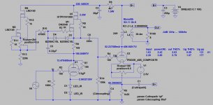
The 250 ohm can kill your tube immeadly
Just loose the interstage and run the C3G as intended, like a penthode. I didn't regards its properties but its brother C3M is often used for driving a 300B, so a 2A3 is only downhill 😉
It's unnecessary.
Keep SE simple as much as possible.
A Gyrator works better anyway but I appreciate that some here don't want to put sand in their circuit. 😉
Last edited:
C3g in pentode is a LOT. I know, I did it. Better to use C3m for pentode duty, but it needs 11v for the heaters.
The problem with this circuit is the LOSS due to the weak anode load on the C3g. A gyrator can indeed solve the problem of the load, but then you need to cap couple to the 2nd stage, so no need for the IT...
And I don't think the OP wants to do that.
Crazy idea: Go back to using the 11k Ohm dropping resistor (instead of 15k) on the C3g and remove C2. Maybe just to try it... 😉 Perhaps Euro 21 can run that in spice.
I used dropping resistors with CCS loads in the past to get the right anode voltage. They worked fine and I got lots of swing. Today I don't need to do it since I use BIG heatsinks and gyrator.
Ian
Last edited:
I calculated 22uf with the formula, I would go for a Vishay or Wima DC link no oil
Cathode 1.5k Ohm
45 tube internal resistance 4.6k
R = 1.5k||4.6k = 1.1K
FC = 10 Hz
FC = 1/(2Pi*R*C) or C= 1/(2Pi*R*FC)
C = 1/(2Pi*1100*10) = 0.0000145 F = 15uF -> so 22uF would of course be good.
Crazy idea: Go back to using the 11k Ohm dropping resistor (instead of 15k) on the C3g and remove C2. Maybe just to try it... 😉 Perhaps Euro 21 can run that in spice.
Ian
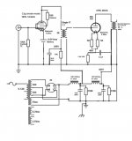
Remove C2? Is this what you are suggesting (see attached)? Or, do you want to have the 11K connected directly to the C3g Anode?
Attachments
A Gyrator works better anyway but I appreciate that some here don't want to put sand in their circuit. 😉
Majority of my VAS stages are gyrator or CCS loaded. 😛
20V.Better to use C3m for pentode duty, but it needs 11v for the heaters.
@ soulmerchant, since the secondary of the IT transformer is open isn't the input tube loaded by the inductance of the the IT primary rather than the arbitrary 5K printed on the schematic? I suppose it would be easy enough to check if it was working with a frequency sweep.
@euro21, you loaded the secondary of the IT in the first sim you posted, how did you derive those values?
@euro21, you loaded the secondary of the IT in the first sim you posted, how did you derive those values?
Disco: Are you suggesting running the C3g (pentode) direct coupled to 45B?
For direct coupling you need to bring the finals' grid at the drivers' anode voltage. That would ask for a much higher PS voltage, like LW did, or a separate negative PS underneath the driver. Another possibility for direct coupling is steering the final through the drivers' cathode. You need to swing quite a high voltage, hence the need for two driver tubes, one as a voltage amplifier and one as a buffer.
The problem with cap coupling arrives when the final starts drawing grid current at peaks, which is only measurable when the coupling cap has a too big value... Here the IT has the advantage because of its low DC resistance but there's always a trade off, hence my recommendation to use the fine properties of a low distortion penthode which uses solely a resistor load, instead of four mosfets 🙂
It's value depends of the IT parameters, the tube's parameters, and the frequency response simulation shows the "linearity" -above few ten kHz-.@euro21, you loaded the secondary of the IT in the first sim you posted, how did you derive those values?
It's only simulated value, but similar (approximately the same) than required "live" damping resitor value.
Youse are quite funny. Now, for a historical, all-time first, so explain the cause and effect these claims about 'bigger' and 'low DCR' actually accomplish and most importantly, how this beard on all the claims made in their favour… 🙂
Then prepare yourselves for a set of examples violating those claims, complete with claims that they sound better.
cheers,
Douglas
Then prepare yourselves for a set of examples violating those claims, complete with claims that they sound better.
cheers,
Douglas
Douglas - we are prepared for your wisdom. Please share.
It was a rhetorical question; I don't believe there is an answer, as I attempted to illustrate by saying that no matter what was said, there would be examples that entirely violated those reasons. And that the counters would also sound good.
cheers,
Douglas
- Home
- Amplifiers
- Tubes / Valves
- Low DCR Chokes: Will it improve transients/dynamics?