A similar point of view goes for you. You can not either know or judge if someone really did hear or not differences, in your example, chokes, capacitors or cables in another set ups. You can not know if there were differences or not, or did the auditory detect any.
When people say they can hear the difference with cable lifters do you believe them? ( or are you one of them).
A simple ABX test will prove if someone, anyone heard a difference. But we never see any. Not even from you. Why not?
My experience, education and logic set of the BS detector and I need proof. Not the usual "proofs" of artifacts at -130db or quantum jibirish but someone actualy hearing a difference (ABX). Do you have any? So all subjective nonsense. You talk about science, do you actualy do any?

My comment was more on the different magnetic properties of silver vs. copper.
From Jack Elliotts page (electra print):
"Copper wire is used to wind transformers due to it being one of the lowest Direct Current Resistance (DCR) of all the metals used to create a magnetic field. Copper is also used to receive the flux variations in the secondary windings. If silver wire is used for the primary, it will create the same field due to the same amount of turns is needed as the copper. The only difference is a lower DCR than the equivalent copper primary, a costly decision for no performance increase.
Silver wire used for the secondary it will be about 200% more sensitive than copper. If the primary has very low level flux motion from higher harmonic content sounds, silver wire will reproduce it. This is the only increase in performance offered by silver wire when used as a secondary."
This effect was reported by many others like Menno v.d.Veen (Amplimo), AE Europe etc.
And further:
"Recently the price of silver has increased to a point that the cost would be prohibitive for many to consider amps delivering the precious metal sound. Electra-Print Audio performed a test to see if the transformer secondary winding needed to be pure silver wire to achieve the sound difference. They determined that partial silver wire or silver plated multi-strand wire was found to be equal to using solid silver wire. The amount of silver needed is just 20% to achieve the improvement in the sound".
from Step Into the Eddie Current Listening Lounge! – Eddie Current
So maybe its not as prohibitive expensive as it initially appears...i would start with an IT to see what happens...
Eddie is a snake oil salesman. Do you actually know how a trnasformer works?
Any transformer will transfer more than 80% of the signal, His magical xformers transfer 200% more or 160% of the signal pulling energy out of his ***. Wheres the measurements and graphs?
If I only new there were so many suckers out there a few years ago, I could easily come up with baffling suedo science to sell useles tweaks for way too much money.
From the leading pro audio transformer manufacturer.
https://www.jensen-transformers.com/wp-content/uploads/2014/08/Audio-Transformers-Chapter.pdf
Silver not mentioned once in 30 pages.
https://www.jensen-transformers.com/wp-content/uploads/2014/08/Audio-Transformers-Chapter.pdf
Silver not mentioned once in 30 pages.
When people say they can hear the difference with cable lifters do you believe them? ( or are you one of them).
It doesn't make a difference to me really. Why not hear if there is? Or why hear if there isn't?
I've played with cable lifters years ago. I used all kinds of cheap stuff - toilet paper rolls, beer cans, coke, partially filled beer cans with dirt, different types of woods.
A simple ABX test will prove if someone, anyone heard a difference. But we never see any. Not even from you. Why not?
Simply because a double blind test with 20 trials, as requested from most communities is quite bothersome, time consuming and expensive. You need to pick up experienced listeners first. Then you need to study the audible difference, if any, so that the listeners can be trained to distinguish the specific differences. When these listeners finally feel psychologically confident enough, you also need to study if the test must be split between long breaks in case their auditory memory saturates. From experience I suspect this test might take days, or even weeks to study and complete.
What others in our community and I have participated are quick simple blind tests with swaps of black boxed DUTs or devices tested behind blankets.
In the past I bothered sharing the results of a few tests in other forums, and due to the reason of them being rejected due to not obeying the DBT and the 20 trials rule, I stopped. IIRC, one test was a double swap of power cables
Eddie is a snake oil salesman. Do you actually know how a trnasformer works?
I avoid using epithets and try maintaining diplomacy, but I agree with you on the point his post doesn't make sense to me either.
From the leading pro audio transformer manufacturer.
404 Not Found
Silver not mentioned once in 30 pages.
Doesn't make a difference either, really. Just because a reputable manufacturer doesn't use a specific material doesn't make it criminal to do. Not everyone likes to experiment.
Last edited:
silver
Really? Check page 6....
I know the Vancouver area had been struck by heat; you did not manage to escape??😉
From the leading pro audio transformer manufacturer.
https://www.jensen-transformers.com/wp-content/uploads/2014/08/Audio-Transformers-Chapter.pdf
Silver not mentioned once in 30 pages.
Really? Check page 6....
I know the Vancouver area had been struck by heat; you did not manage to escape??😉
Ian - the amp is up and running. The IT secondary is grounded. And the 45B is measuring 59V on the filaments. The existing schematic is shown below reflecting some changes recently made.
Ahhh and the cathode resistor is 1.8k now too. So you are running around 33mA.
The plate curves suggest at 33mA, and -60V bias, the plate would be at around 290V. Add 60V to that to get the actual plate voltage. That makes it 350V.
But in your schematic I see 410V... strange, but ok.
Also in your schematic, I see this 11k ohm dropping resistor from the HT to the input/driver stage. You are using a (very nice) 5k 1:1 transformer as the load for your triode strapped C3g.
C3g plate resistance in triode is about 2.3k Ohm (at roughly 15mA - Siemens specs sheet). So... what do you think about this? How much amplification factor is lost with this modest 5k load do you think?
I don't want to be too critical. There are lots of ways to do things. I have my ideas, but others here are also able to make very good suggestions.
Best regards
Ian
Last edited:
Really? Check page 6....
I know the Vancouver area had been struck by heat; you did not manage to escape??😉
The sentence on page 6 is:
Sometimes silver wire is suggested to replace copper, but since its
resistance is only about 6% less, its effect is minimal and certainly not cost-effective.
Not really a ringing endorsement. I have built many wonderful amplifiers over the years. Not a single one uses silver wound transformers (but I am sure they are very nice too).
Ian
Last edited:
Also, you are running ultra-path with only 5.6uF - I guess the 45 has a high enough plate resistance for this to work. I might try a bit more though.
oh yeah... and a 1k ohm grid resistor on the 45 is also a good idea. But you probably know this.
You might want to temporarily try this kind of arrangement (ignore the fact that it is push-pull, and the negative rail on the secondary):
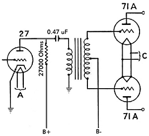
Yes, it will require a coupling capacitor. But then you can use a larger value resistive load on the plate. Maybe you can re-purpose the 11k dropping resistor for the load (needs checking). You might be surprised with the result.
Best regards
Ian
oh yeah... and a 1k ohm grid resistor on the 45 is also a good idea. But you probably know this.
You might want to temporarily try this kind of arrangement (ignore the fact that it is push-pull, and the negative rail on the secondary):
Yes, it will require a coupling capacitor. But then you can use a larger value resistive load on the plate. Maybe you can re-purpose the 11k dropping resistor for the load (needs checking). You might be surprised with the result.
Best regards
Ian
Last edited:
Ian - good questions / suggestions. Thanks. I am running ultra-path just recently (I believe Friday - 2 days ago) and the only cap I had was 5.6uF, other than the 50uF PIO Russian that it was replacing. I wanted to determine if the Jantzen Supreme cap 5.6uF would sound better / different than the 50uF Russian PIO. Answer: Yes, but don't know if the capacitor value or capacitor make Russian PIO vs. Jantzen Supreme is the difference maker. I do understand that the 5.6uF is too low in value. The 5.6uF had lower output, cleaner mids and highs. While the 50uF Russian PIO had higher output, but was slower and veiled. Ultimately, I want to use fixed bias and get rid of as many caps from the audio circuit as possible.
Regarding the 45B output tube. The Vdc at anode measures 410V. Bias measured at top of 1.8K cathode resistor is 59V. So the plate would be 411-59=352V, correct? Also, my ammeter indicates 46mA. Does this sound correct?
Regarding the C3g plate resistance and impacts amplification factor, I do not understand this concept so please share your thoughts.
Thanks!
From experience, we lately compared a silver vs copper input tranny with the other materials like core and insulation being kept the same.
It was enough to make a total system sound overhaul.
So you are apparently smarter than Rupert Neve. (was).
(RIP February 12, 2021).
Congratulations! 🙄
Why don't you work for mixing console designers?
Studio engineers are desperate for people with such "golden" ears.
I've neither known Mr. Neve (RIP), neither I would qualify myself for being "smarter" from him or anyone else. Why would you attempt comparing two people you probably don't know well enough?
I chose hi-fi audio transformer design, because it's exotic and rare. Since youth I started looking for exotic interests, one of my first hobby was DIY pyrotechnics, fireworks and explosives.
I chose hi-fi audio transformer design, because it's exotic and rare. Since youth I started looking for exotic interests, one of my first hobby was DIY pyrotechnics, fireworks and explosives.
Really? Check page 6....
I know the Vancouver area had been struck by heat; you did not manage to escape??😉
Instead of being an ahole, what do they say about it?
Ian - good questions / suggestions. Thanks. I am running ultra-path just recently (I believe Friday - 2 days ago) and the only cap I had was 5.6uF, other than the 50uF PIO Russian that it was replacing. I wanted to determine if the Jantzen Supreme cap 5.6uF would sound better / different than the 50uF Russian PIO. Answer: Yes, but don't know if the capacitor value or capacitor make Russian PIO vs. Jantzen Supreme is the difference maker. I do understand that the 5.6uF is too low in value. The 5.6uF had lower output, cleaner mids and highs. While the 50uF Russian PIO had higher output, but was slower and veiled. Ultimately, I want to use fixed bias and get rid of as many caps from the audio circuit as possible.
Caps are not much of a problem. I think working on your schematic will make a much bigger difference. Once you experience what these two valves/tubes can do, you will be surprised. 😉
Regarding the 45B output tube. The Vdc at anode measures 410V. Bias measured at top of 1.8K cathode resistor is 59V. So the plate would be 411-59=352V, correct?
Yes, so now look at the plate curves for your 45B

Your quiescent operating point is roughly where the -60V curve intersects with 350V (This looks to be something like 75ma)
Also, my ammeter indicates 46mA. Does this sound correct?
Learning Ohm's law by heart is a must-do in this hobby. You have 59V /1.8k Ohm = 32.8 mA. Ohm's law never lies.
I hope you know how to correctly measure DC current with the ammeter. You would need to detach your cathode resistor's ground connection (break the circuit) and insert the meter in series with it (make sure the negative terminal is well grounded). I never do this for any circuits with any high voltages, since we have Ohm's law. Lots of older analogue ammeters were broken with to high current in the past...
Now... there is a big difference.. between 75mA (plate curves) and 46ma (measured?) and the actual value of 33mA. Either the plate voltage is different or there is another explanation.
I have an idea of what this explanation is but you won't like it. Basically your supply can't push the B+ higher. And if it could, it would burn out your 45b valve/tube. Think of this is as just a possibility... (been there, done that).
Regarding the C3g plate resistance and impacts amplification factor, I do not understand this concept so please share your thoughts.
Ok, so the C3g plate resistance is roughly 2.3K ohm and your load is only 5K ohm. back when I did things old-school, I preferred a load of at least 3x the internal (plate) resistance of the tube/valve.
In very lay-man terms (my daughter hates when I say that word), this helps reduce the amount of amplified signal loss through the de-coupling cap (in your schematic the Wima MKP 30uF) . Said differently, your driver will drive a lot more if the load is greater. It will "Swing" more AC volts with a bigger load (again, you can prove this to yourself by using Ohm's law).
But you need to design it. You can't just use any old big value resistor, since there will be DC drop across it too.
Looking at the Siemens specs sheet for C3g, a nice linear load line would be at least 10k Ohm. This would make it parallel to the plate curves. So your 11k Ohm resistor should work, as long as the B+ is correct.
If the B+ is too high, your C3g plate voltage will be too high. 16mA*11k ohm = 176V drop across that resistor. Your B+ is probably something like 420V or so, right? That would put the C3G plate at 244V, which is kinda hot for 16mA on C3g.
So that brings up my other concern.. you have 2.5V Zener or LED bias on your C3g, right? and the plate is 210V ? Look up that point on the C3g triode-connected plate curves from the siemens specs sheet.
So yes, your amp is working. Is it working at correct operating values to get the most out of your tubes? I don't think so. Valves/tubes are wonderful devices since they tolerate so much. Building solid-state without good design always fails. 😉
Coming from experience, designing even a good single end amplifier takes a bit of work. I spend a lot of time going over operating points, plate curves, comparing different potential components electrical characteristics before I even think about starting to build.
But then my results are really darn good. The driver swings as it should and even components that others say sound crap (insert marketing garbage claim of choice here) do something magical.
A well designed amplifier made of modest components will 100% hands-down beat a poorly designed one with expensive boutique stuff every time.
Thanks!
Feel free to PM me. At some point you will probably realize that you need to work on the power supply, after figuring out your B+ is too high for what you need/want to do....
Last edited:
Instead of being an ahole, what do they say about it?
Sometimes silver wire is suggested to replace copper, but since its resistance is only about 6% less, its effect is minimal and certainly not cost-effective.
That said, I have seen some of the stuff 50AE has designed and built before. You need to design and build stuff at his level FIRST, then consider if you need to get to that next level.
For this project, I would put it way down the list of things to consider.
Last edited:
Slight problem,- all the mixing desks used to supply the music you listen to, use OPAMPS and silicon.I have seen some of the stuff 50AE has designed and built before. You need to design and build stuff at his level FIRST, then consider if you need to get to that next level.
Being as your speakers don't even have the resolution of 16bit audio, how on earth can you not know you are simply listening to different iterations of distortion?I chose hi-fi audio transformer design, because it's exotic and rare.
As for Rupert, I know what he believed in, and what was his ethos.
He simply wasn't interested in stuff which could
1/ not be replicated and measured.
2/ make sure he was adamant in finding the absolute best product and solution for his applications.
I also happen to know particularly well what he personally believed, and he was no atheist, which makes me know a lot more about him than you ever will.
Last edited:
Hi Sarcastic1
Nothing wrong with silicon. I use it all the time. Just because the mixing console used silicon for recording, mastering, EQ, etc... you think there is no point in using valves/tubes for playback? Maybe I am missing your point.
I don't see the point in using silver wired transformers for my designs and builds. But if someone else wants to, that is their business. If they claim it is better, then that is good for them. I don't like to challenge people with "talented" hearing as it is pointless.
Nobody else on this thread seems interested in helping the OP with his sub-optimal design, which is where his problem really is.
It would be nice to read your suggestions on how the OP can improve his circuit with his parts on hand.
Ian
Slight problem,- all the mixing desks used to supply the music you listen to, use OPAMPS and silicon.
Being as your speakers don't even have the resolution of 16bit audio, how on earth can you not know you are simply listening to different iterations of distortion?
What you fail to understand again and again is, in this thread a certain group of people is discussing phenomena we claim we've heard. Of course we lack an absolute proof to the world our phenomenas are audible, but neither you do have a proof to justify so. Or at least you can still believe you have one.
You are still attempting to associate aspects, such as the 16 bit speaker thing being as a fresh example, to prove or partially prove the phenomenas we claim to be experiencing. And you lack a proof there's is a justified relation, while you believe there is.
I'm not attempting to shake the structures of your beliefs, but if you somehow suspect you might do the same for the current discussion in this thread, you're most probably mistaken.
I also happen to know particularly well what he personally believed, and he was no atheist, which makes me know a lot more about him than you ever will.
Doesn't matter, really. At least for me. Not sure why you're insisting of using such arguments. Neither I find a relation with Rupert's beliefs. His beliefs are not a proof, neither are yours.
Last edited:
- Home
- Amplifiers
- Tubes / Valves
- Low DCR Chokes: Will it improve transients/dynamics?