Bought an inexpensive hot air soldering gun and took less than 2 minutes to remove the 4700 regulator, cleaned the trace and will order a replacement.
could you please post a photo with the bottom of the regulator?
Skylab
Can you tell me the resistor value for R1 and R4 on spdif input?
If i see correctly you have R1..75ohm and R4...100kohm??
Can you tell me the resistor value for R1 and R4 on spdif input?
If i see correctly you have R1..75ohm and R4...100kohm??
Last edited:
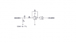
R1,2,3 = 100k
R4,5,6=75r
Me and Cmiu007 built 4 kits of this DAC and the Spdif input never worked. As Cmiu007 already said feed the DAC with SPDIF TTL level thru IC1 isolator and it should work.
Anyway the Spdif input is not a good implementation as the digital source should see a 75ohmm termination and is not like this.
Last edited:
When you say the op-amp in the middle, do you mean the output opa-amp, or the one supplying Avcc to the DAC chip?
I was referring to IC12.
could you please post a photo with the bottom of the regulator?

This is the hot air gun I bought for $50US, well worth the money, quiet and fast.

Skylab
Can you tell me the resistor value for R1 and R4 on spdif input?
If i see correctly you have R1..75ohm and R4...100kohm??
Hi,
The R4 measured 77R and could not get a reading the R1 and R4.
Last edited:
Skylab
and others... I have never seen that spdif level shifter is made in such resistor values. Digital signal must have 75ohm impedance.
So try to switch resistors... 75 goes to ground... so R1 is 75ohm
R4 is ....ocassionally 100R but i dont know what kind of ic it is. With scope you must get about 5v ttl level on output. If it is too low try smaller R4 resistor value.
you need to install ic1 and power it, both sides. and put s2 on off

Hi,
See the two yellow high lighted box on ground and BK which should map to the GND and BCK output pin of the isolator, can I just hotwired them to the spdif input directly (bypassing the isolator) and with S2 set to OFF ?
Skylab
and others... I have never seen that spdif level shifter is made in such resistor values. Digital signal must have 75ohm impedance.
So try to switch resistors... 75 goes to ground... so R1 is 75ohm
R4 is ....ocassionally 100R but i dont know what kind of ic it is. With scope you must get about 5v ttl level on output. If it is too low try smaller R4 resistor value.
OK, wilk try and report back.
Thanks
Hi,
See the two yellow high lighted box on ground and BK which should map to the GND and BCK output pin of the isolator, can I just hotwired them to the spdif input directly (bypassing the isolator) and with S2 set to OFF ?
more like this - s2 off / s1 on
the picture is for i2s/dsd setup
An externally hosted image should be here but it was not working when we last tested it.
Hi,
The R4 measured 77R and could not get a reading the R1 and R4.
Correction
The R4 measured 77R
R7 1K
R1 100K
Meter ran out of battery.
Skylab
and others... I have never seen that spdif level shifter is made in such resistor values. Digital signal must have 75ohm impedance.
So try to switch resistors... 75 goes to ground... so R1 is 75ohm
R4 is ....ocassionally 100R but i dont know what kind of ic it is. With scope you must get about 5v ttl level on output. If it is too low try smaller R4 resistor value.
no use as the data pins that comes from ic6 have 3v, i presume that because of poor soldering of the chip, the data entry part is faulty - this may be the explanation why some dacs works for 5 minutes and afterwards distorsion apears or in my case one chip burned and the other two works only thru isolator. direct data feeding does not work.
Skylab
and others... I have never seen that spdif level shifter is made in such resistor values. Digital signal must have 75ohm impedance.
So try to switch resistors... 75 goes to ground... so R1 is 75ohm
R4 is ....ocassionally 100R but i dont know what kind of ic it is. With scope you must get about 5v ttl level on output. If it is too low try smaller R4 resistor value.
The IC is 74HC1GU04
A. direct feed - no lock
B. thru i2s isolator - stable lock (before and after the isolator - i don't remember which is which, but does not matter as they are almost identical)
An externally hosted image should be here but it was not working when we last tested it.
B. thru i2s isolator - stable lock (before and after the isolator - i don't remember which is which, but does not matter as they are almost identical)
An externally hosted image should be here but it was not working when we last tested it.
no use as the data pins that comes from ic6 have 3v, i presume that because of poor soldering of the chip, the data entry part is faulty - this may be the explanation why some dacs works for 5 minutes and afterwards distorsion apears or in my case one chip burned and the other two works only thru isolator. direct data feeding does not work.

One thing I don't quite get, the trace coming from the isolator and the direct spdif (IC2) both goes to the same pin under R10, technically if the pin soldering is faulty then both should failed.
When I use the first direct spdif input, I got a solid lock but distorted sound.
A. direct feed - no lock
B. thru i2s isolator - stable lock (before and after the isolator - i don't remember which is which, but does not matter as they are almost identical)
Is it possible due to a faulty invertor IC2/3/4? or just a plain bad implementation?

Is it possible due to a faulty invertor IC2/3/4? or just a plain bad implementation?
i didn't desoldered them yet, i'm still waiting to replace the burned k2m chip.
it's a little probability to have 4 faulty ic's on 4 boards (atupi's included)
later edit: i'm keeping the working ones as they are for the moment
Last edited:
- Status
- Not open for further replies.
- Home
- Source & Line
- Digital Line Level
- Low cost ES9018 Dac - Builders Thread