Hi Wg45,
Yes, sounds like a great idea if you can handle the GB on the adapter PCBs in combination with the LU1014D’s. We will incorporate ZM’s suggestion of side mounting holes. We will get you the Gerber files etc in next day or so.
Thanks,
X
Yes, sounds like a great idea if you can handle the GB on the adapter PCBs in combination with the LU1014D’s. We will incorporate ZM’s suggestion of side mounting holes. We will get you the Gerber files etc in next day or so.
Thanks,
X
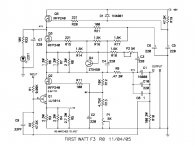
The attached F3 schematic indicates that the bias conditions are Vds 2.4v and Ids 1.5A. I plan to perform a Vgs-Id curve at Vds=2.4V. I can obtain transconductance and Rds while performing the sweep. The measured parameters will be Vgs, Vpinch, Rds and transconductance at Vds=2.4V and Ids=1.5A.
We shall see what the population distribution looks like after some numbers of devices are finished characterization.
My suggestion is for the group buy to acquire 200pcs to 300pcs from Mr. Pass which should yield 100 to 150 matched pairs. If any are left over, we can send them back to Mr. Pass or send them to the DIY store.
For those who want to play at home, you can buy the LU1014 from an eBay seller and I will enumerate how to do the matching at home. If you want to know which eBay seller, just send me a private message.
This will not happen overnight. It will be a process to do the matching and refine the procedure for mass consumption.
Attachments
Last edited:
why are we so hung up on reflowing low temp solder? if two side holes are provided why not put a clamp across the LU and just use a thermally conductive paste to the metal substrate? there may be issues with embrittlement on that solder layer.
soldering - Any drawbacks to "low temp" lead-free solder paste? - Electrical Engineering Stack Exchange
great idea to synch the GB of matched fets and the adapter board.
soldering - Any drawbacks to "low temp" lead-free solder paste? - Electrical Engineering Stack Exchange
great idea to synch the GB of matched fets and the adapter board.
Last edited:
We could also use Sn/Pb paste and heat it to about 200C and it will also work well. I think the new paste with Sn/Bi/Ag is less brittle. ENIG finish might be more appropriate if using low temp solder to prevent “Pb poisoning”.
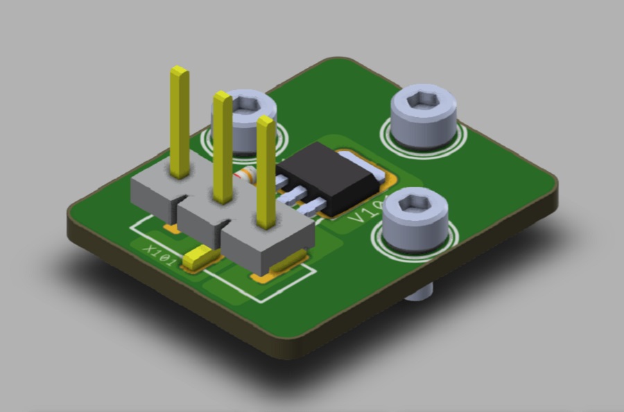
A big thanks to JPS64 for making the design for LU1014D to TO247 adapter in IMS. Full manufacturing data is availble here. I will order a few to make a verification build and wg45 will then provide them as part of this GB as an option.
I am curious about the thickness of the assembly vs. the thickness of an ordinary TO247. Is there a dimensioned drawing of the LU adapter assembly?
What about a through-hole mounting of the 3-pin header? A surface mount header may be difficult to align so that it is straight enough.
We want the PCB to be flat and smooth on the bottom for good heat transfer to the heatsink. So through hole is not possible if we want it smooth on the bottom. Note that the metal PCB is conductive and holes and vias in general, are to be made conductive to the substrate. Most IMS PCBs are strictly SMT. The soldering of the 3-pin header should not be hard using paste and a hot plate. Once it melts use a tweezer to nudge it around to align with the pads. Then cool it to lock in place. The pads have solder mask and are well defined.
The IMS board is between 1.6mm and 2mm thick. The SMT header is a standard part - you can look it up with the part number. JPS64 might have the part number handy.
The dimensioned drawing is in the manufacturing zip file I believe.
The pin headers use 1.14mm square pins spaced 0.200in apart.
The IMS board is between 1.6mm and 2mm thick. The SMT header is a standard part - you can look it up with the part number. JPS64 might have the part number handy.
The dimensioned drawing is in the manufacturing zip file I believe.
The pin headers use 1.14mm square pins spaced 0.200in apart.
Last edited:
We want the PCB to be flat and smooth on the bottom for good heat transfer to the heatsink. So through hole is not possible if we want it smooth on the bottom. Note that the metal PCB is conductive and holes and vias in general, are to be made conductive to the substrate. Most IMS PCBs are strictly SMT. The soldering of the 3-pin header should not be hard using paste and a hot plate. Once it melts use a tweezer to nudge it around to align with the pads. Then cool it to lock in place. The pads have solder mask and are well defined.
The IMS board is between 1.6mm and 2mm thick. The SMT header is a standard part - you can look it up with the part number. JPS64 might have the part number handy.
The dimensioned drawing is in the manufacturing zip file I believe.
The pin headers use 1.14mm square pins spaced 0.200in apart.
Excellent info. Thank you. How about a soldering jig for holding the header pins in place while soldering?
Well, materials bonded with H20E (assuming you consider their CTE´s) survive thermal shock- htol- htb- and other tests just fine, otherwise who would use such an epoxy.
Read publications abot the subject if you´re interested but don´t post singular values out of datasheet or wherever if you don´t know what they mean or if they are even remotely relevant. Obviously you lack the experience working with such polymers and are certainly not part of the semiconductor-industry.
I appreciate your experience, but in my real job I manage a world class mechanical property testing lab. My personal experience with H20E is that it becomes extremely brittle at room temperature after a small number of thermal cycles within it's datasheet operating temperature.
Worth noting: I love my F3.
It's the best amplifier I've ever built and I keep coming back to it. I found a nice sweet spot in the set-up with just enough feedback, and it just sings.
The power supply has gotten noisy now, and I'm a bit upset with myself that I re-used some old EI transformers that have developed a ton of mechanical hum that is now coming out of the speakers.
@EU,
i talked with wg45 and if enough people come together, I will take over the distribution within the EU (as last time). 🙂
If it not so much interested people in EU then I think shipping from US is also possible.
i talked with wg45 and if enough people come together, I will take over the distribution within the EU (as last time). 🙂
If it not so much interested people in EU then I think shipping from US is also possible.
If these are not super expensive ones compared to other exotics like SemiSouths, I would be in, as EU citizen.
Quick check for Latvia shipping costs 4€ in a padded envelope (without tracking and no insurance), think that would be also possible.
Let us see what is possible for our continent. ;-) I will talk then with wg45 after the interested list is closed.
Let us see what is possible for our continent. ;-) I will talk then with wg45 after the interested list is closed.
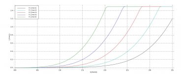
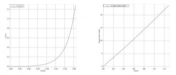
I am getting started creating the setup for matching devices. Attached are family of curves and transconductance measurements for one of the devices in my personal stash. I had to resort to 6-wire connection to make the D-S measurement 4-wire Kelvin.
I can see that I need to measure beyond 1.5A which will cause a re-stacking of instruments and recabling.
I can see that I need to measure beyond 1.5A which will cause a re-stacking of instruments and recabling.
Attachments
Excuse me if I stepped on your toes. It didn´t sound as you have experience in the field.I appreciate your experience, but in my real job I manage a world class mechanical property testing lab. My personal experience with H20E is that it becomes extremely brittle at room temperature after a small number of thermal cycles within it's datasheet operating temperature.
And thanks a lot for your view. It´s very intriguing to me as I dare say that "half of our company is built on H20E" and that epoxy has seen many qualification tests over the years.
No sign of brittleness at all. Only problem we sometimes have is silver migration but only under extreme enviromental circumstances.
And sure nowadays, there is a much bigger choice in epoxys. Especially when it comes to thermal resistance. At the time H20E was the best compromise for us, AFAIK priority was electrical conductivity.
Hi, how do I register and pay for a pair of fets?
Do you know roughly when they'll be available?
Will you be offering world wide shipping?
Thanks in advance!
Do you know roughly when they'll be available?
Will you be offering world wide shipping?
Thanks in advance!
Hi, how do I register and pay for a pair of fets?
Do you know roughly when they'll be available?
Will you be offering world wide shipping?
Thanks in advance!
The GB sign up sheet should go live next week, on this thread.
The same posting will have details on cost. Payment will be through Paypal.
I'm guessing it will take a few weeks to match and ship the Power Jfets. Carsten will handle distribution to the EU. I'll handle shipping to the Americas and rest of the world.
- Home
- Group Buys
- Lovoltech LU1014 Power Jfet Group Buy