So my conclusion, for my system and my ears, is that cabinet edge diffraction has an effect that goes beyond its impact on frequency response. It affects the 3 dimensional quality of the music, but only with music that has preserved that aspect through the recording/reproduction process.
+1
Worded much better than I did, this is what I meant to say.

I have monitored the RAM usage and it does occasionally get close to being used up but never maxed out, so that isn't a particular issue for me. The size of the RAM needed scales to the volume of space the simulation occupies, the bigger the model the more memory is needed to describe it.Slightly off topic but...
In your case, I suspect that 16 GB of RAM is not enough to keep CPU happy. I bet the CPU is using disk space as an overflow. With a mechanical hard drive this can get super slow, but even with a solid state hard drive it is much slower than RAM. For our application, we found we needed at least 64 GB of RAM to max out the capability of an i7 processor. Otherwise the CPU spent a lot of time waiting for reads/writes to the disk.
I don't find the time it takes for that detailed a simulation to be a problem. The time it takes to get everything else right dwarfs it in comparison.
Edge diffraction has an impact on '3 dimensional quality' as referred to above. Edge diffraction may reduce off-axis energy. This means there are less 'far reflections' that would come to your ears a bit later then direct signals (on axis). This delay creates the sensation of 3D sound and is directly related in our ability to spot the source of something based on sound (in essence, its echo-location). So, speakers that have better off axis response sound better 🙂
The latest version of ATH allows us to simulate waveguides in enclosures, so now I can evaluate this behavior with a lot more rigor than was possible two years ago. Basically I was doing sims with AXI Driver in 2020, but ABEC is much better for this.

This is a JBL 708P. It's a two way speaker with an 8" woofer and a waveguide that's about 10" in diameter.

Here's a two way I've been working on using ATH. Waveguide is about 17" larger. Enclosure size is comparable.

Here's the horizontal polars of the JBL 708P, courtesy of Erin's Audio Corner. Though the waveguide should "theoretically" control beamwidth down to 1350Hz, we see directivity control all the way down to 200Hz. And I think that's due to the dimensions of the cabinet.

Here's the predicted horizontal polars of the design I made. In the prediction, we can see that directivity control goes much lower than one might expect. These polars are normalized.

These are the unnormalized polars. Quite smooth, if I do say so myself.

Here's the measured vertical response of the JBL 708P, courtesy of Erin's Audio Corner

Here's the predicted vertical response. In particular, note how the widening of directivity in the midrange appears to be caused by enclosure shape. This is tricky, because it really seems that the vertical offset of the drivers will make a large difference in frequency response and polar response and I haven't seen a lot of discussion of this. Possibly because it's been hard to simulate this, up until a week ago, and I doubt many people build six seperate loudspeaker enclosures and then pick the one that "sounds the best." We just stick drivers in a box and don't pay a whole lot of attention to where they're located. But it looks like the location of the drivers, shape of the baffle, and depth of the enclosure is very important.

Starting to think this shape isn't just cosmetic...
FYI - going forward I think I will be using the same graph parameters that Erin is using, so that it's easier to compare predicted data to measured data. So in the sims I did, the sims are for zero to ninety degrees on the horizontal axis. For vertical measurements, it's zero to forty degrees. Vertical scale is 50dB - same as his measurements.
This is a JBL 708P. It's a two way speaker with an 8" woofer and a waveguide that's about 10" in diameter.
Here's a two way I've been working on using ATH. Waveguide is about 17" larger. Enclosure size is comparable.
Here's the horizontal polars of the JBL 708P, courtesy of Erin's Audio Corner. Though the waveguide should "theoretically" control beamwidth down to 1350Hz, we see directivity control all the way down to 200Hz. And I think that's due to the dimensions of the cabinet.
Here's the predicted horizontal polars of the design I made. In the prediction, we can see that directivity control goes much lower than one might expect. These polars are normalized.
These are the unnormalized polars. Quite smooth, if I do say so myself.
Here's the measured vertical response of the JBL 708P, courtesy of Erin's Audio Corner
Here's the predicted vertical response. In particular, note how the widening of directivity in the midrange appears to be caused by enclosure shape. This is tricky, because it really seems that the vertical offset of the drivers will make a large difference in frequency response and polar response and I haven't seen a lot of discussion of this. Possibly because it's been hard to simulate this, up until a week ago, and I doubt many people build six seperate loudspeaker enclosures and then pick the one that "sounds the best." We just stick drivers in a box and don't pay a whole lot of attention to where they're located. But it looks like the location of the drivers, shape of the baffle, and depth of the enclosure is very important.
Starting to think this shape isn't just cosmetic...
FYI - going forward I think I will be using the same graph parameters that Erin is using, so that it's easier to compare predicted data to measured data. So in the sims I did, the sims are for zero to ninety degrees on the horizontal axis. For vertical measurements, it's zero to forty degrees. Vertical scale is 50dB - same as his measurements.
The blades?Starting to think this shape isn't just cosmetic...
The shae is very purposeful. Very smooth, large radii, push-push loading of woofers symmetrically around the mid/tweeter.
I wonder how they could be detailed with a DSP XO and time delays and such to get everything in time. I have built a miniMe with the same ideas (but not as elegantly done, i think these things ae very pretty.
Or, if you are going to rip it a part (ie rich enuff), take it a step further and put a MAOP in the place of the coax.
dave
The Blade shape definitely have been thoughts about. Such as the Muon ( i don't find them as nice looking as Blade, but the shape is even more optimised for acoustic behavior).
Dave what do you mean about dsp ( i fear i'm lost in translation)? And what MAOP means?
Dave what do you mean about dsp ( i fear i'm lost in translation)? And what MAOP means?
Last edited:
Well, it surely is ( the chrome finish doesn't help) but for diffraction it push things even further than Blade in my view.
It is interesting how Kef present range evolve: the attention given to box goes up the closer you come to flagship ( if Muon is considered as is).
But Blades integration of technological choices and overall shape is very clever in my view making them special.
It is interesting how Kef present range evolve: the attention given to box goes up the closer you come to flagship ( if Muon is considered as is).
But Blades integration of technological choices and overall shape is very clever in my view making them special.
Muon is a bit weird,

DSP, digital XO/EQ. MAOP 10.2
I have never gotten a handle on the acronym, but the M stands for metal. An aluminum alloy cone is bombarded with electrons to turn the top few molecules thick layer is turned into a ceramic.
dave
DSP, digital XO/EQ. MAOP 10.2
I have never gotten a handle on the acronym, but the M stands for metal. An aluminum alloy cone is bombarded with electrons to turn the top few molecules thick layer is turned into a ceramic.
dave
Well it certainly brings that diffraction on.. early.it push things even further
Sorry Dave i wasn't clear in my question about dsp: what do you mean by 'how they could be detailed'.
Because i don't see anything very different from another three way including a coax. Maybe the quad push/push might induce something i'm not aware of ( and given your experience with the principle you could well be) but at wavelength involved they should behave as one source.
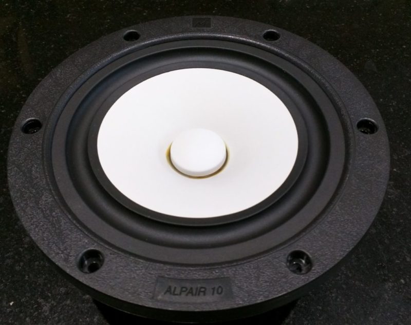
Thank you for MAOP, i missed this Mark Audio driver. How does it compare to Alpair7 gen2 ( i own a pair)?
Allen please apologise, i don't get your comment ( i had a long day of work and i'm tired so not in my best). Do you mean the contoured 'toro' shape of Muon would bring more diffraction? From this kind of vertically aligned loudspeakers this kind of shape seems to be regularly used in design trying to minimise diffraction.
Because i don't see anything very different from another three way including a coax. Maybe the quad push/push might induce something i'm not aware of ( and given your experience with the principle you could well be) but at wavelength involved they should behave as one source.
Thank you for MAOP, i missed this Mark Audio driver. How does it compare to Alpair7 gen2 ( i own a pair)?
Allen please apologise, i don't get your comment ( i had a long day of work and i'm tired so not in my best). Do you mean the contoured 'toro' shape of Muon would bring more diffraction? From this kind of vertically aligned loudspeakers this kind of shape seems to be regularly used in design trying to minimise diffraction.
Time align the drivers (woofers & mid should already be), and make the XO phase coherent.
Push-push produces very low vibrational load to the loudspeaker box, 4 instead of 2 means they can be arranged symetrically around the midTweeter.
The MAOP 7 is actually based on A7.2, it is a decied upgrade from any stock A7.x, A7.3eN get sreally close, but MAOP is a bit less coloured. I may EnABL the pair i have, which should take them to another level. The current darling is the MAOP10.2 which is a more appropriate size for the box.
dave
Oh yes, i'm with you for the dsp approach. FIR even ( i use complementary FIR filters, no manipulation still ( 'room correction') but the more i learn about the more i'm curious).
I'm convinced with push push benefits. Been curious about the Tysen (iirc) some years ago, tried something inspired (not with 1/4 line/aperiodic though, closed box) and got nice results.
I'm convinced with push push benefits. Been curious about the Tysen (iirc) some years ago, tried something inspired (not with 1/4 line/aperiodic though, closed box) and got nice results.
In regards to my previous post: https://www.diyaudio.com/community/threads/loudspeaker-enclosures-are-waveguides.363630/post-6994035
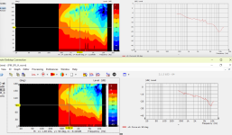
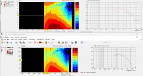
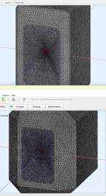
Here is a sim of this enclosure when it's 20cm deep

Here is a sim of this enclosure when it's 40cm deep
The differences are subtle. Energy cannot be created or destroyed and all that. In the enclosure that's 40cm deep, we see that the beamwidth is narrower at lower frequencies. Note how the beamwidth at 600Hz for the 20cm deep enclosure is 160 degrees, and for the 40cm deep enclosure it's 140 degrees.
I'm going to go out on a limb and speculate that the average listener can't perceive a difference between a beamwidth of 160 and 140 degrees at 600Hz.
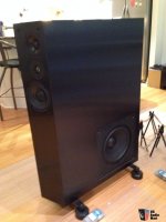
Ultra deep speakers like the NHT 3.3 (see attached) likely used a deep enclosure to increase the efficiency of the subwoofer that was located in the base of their enclosure. Particularly since the subwoofer in the NHT 3.3 had an efficiency of somewhere around 82dB.
Here is a sim of this enclosure when it's 20cm deep
Here is a sim of this enclosure when it's 40cm deep
The differences are subtle. Energy cannot be created or destroyed and all that. In the enclosure that's 40cm deep, we see that the beamwidth is narrower at lower frequencies. Note how the beamwidth at 600Hz for the 20cm deep enclosure is 160 degrees, and for the 40cm deep enclosure it's 140 degrees.
I'm going to go out on a limb and speculate that the average listener can't perceive a difference between a beamwidth of 160 and 140 degrees at 600Hz.
Ultra deep speakers like the NHT 3.3 (see attached) likely used a deep enclosure to increase the efficiency of the subwoofer that was located in the base of their enclosure. Particularly since the subwoofer in the NHT 3.3 had an efficiency of somewhere around 82dB.
Attachments
There is more than just a beamwidth difference. Look at the 90 degree curve that shows the off axis diffractive hump that comes with all cabinets. It becomes lower in frequency with the deeper cabinet, but it also becomes higher in level relative to the on and near axis responses. It also changes the amount of sound that goes in which direction. If you put some observation fields in your simulations you will literally be able to "see" the shape of the directivity at different frequencies.I'm going to go out on a limb and speculate that the average listener can't perceive a difference between a beamwidth of 160 and 140 degrees at 600Hz.
Inspired by Perry Marshall: https://www.diyaudio.com/community/threads/constant-directivity-without-horns-or-waveguides.422090/
I decided to resurrect this thread.
EDIT: The difference in these graphs is subtle, so let me point a couple things out that may not be obvious. The first is that my measurement technique that I've been using for 2+ decades, it looks like I need to step my game up. Basically, I've done nearly all of my measurements in +/- 45 degrees, measuring 90 degrees of beamwidth. I figured that was sufficient for a waveguide, since most of my waveguides have been narrow, over the years. I've made lots of Unity-horn-inspired stuff, and it's beamwidth is 50-60 degrees, depending on the model. What these ABEC sims show, is that the enclosure impacts beamwidth, but you need to look ALL THE WAY out to +/- 180 degrees, a full 360 degrees around the design. There, we can see that radiation to the sides is impacted by what's happening at the FRONT of the baffle.
I've made a lot of threads about roundovers and minimizing diffraction, and often found that a roundover didn't seem to make much of a difference if the waveguide is large. What I'm seeing here is that it DOES make a difference, but you really need to widen your measurement and simulation window beyond +/- 45 degrees.
Attached are five files:
First, there are pics of two different Unity waveguides, which are mounted in an enclosure. One of the enclosures has a modest roundover - 1" or 25.4mm - while the second enclosure has a larger bevel on it. I was curious to see if a roundover is always superior to a bevel. Particularly since the use of a bevel simplifies building the baffle by quite a bit. It's way easier to cut a 45 degree bevel into a wood baffle, than it is to 3D print a baffle with a roundover.
Next, is a pic illustrating the predicted response of the two enclosures. The first prediction IS normalized. The next one ISN'T normalized. The reason that the difference between "normalized" and "not normalized" are similar is because the beamwidth of this particular design narrows at high frequency. I believe this is due to the fact that 75% of the bandwidth (up to about 2khz) has it's beamwidth determined by the size and shape of the enclosure.
In other words, the shape and dimensions of the cabinet allow the cabinet itself to behave as an extension of the waveguide, but the beamwidth is still quite wide. The waveguide itself maintains pattern control down to 2khz, where the beamwidth is ninety degrees. By 500Hz, two octaves lower, the beamwidth has increased to 150 degrees, but it's not the 180 degree beamwidth you'd expect from an infinite baffle.
Here's the output from running ATH; note that the beamwidth at the throat is 34.340 degrees. I think I may be able to improve the performance by making the entrance angle to the waveguide wider, to reduce the beaming at high frequency.
-calculating profiles
-morphing to rectangle
-morph: adding -5 mm in width
-morph: adding 2 mm in height
-fixed length: 50.8 mm
-stretched to boundary: dx=4.92786 dy=2.43566
-writing ABEC project
-writing geo file bem_mesh.geo
-average mesh throat angle: 17.170 deg
-reading source definition file
-running 'c:\Users\johndoe\Downloads\gmsh-4.11.1-Windows64\gmsh bem_mesh.geo -'
Info : Running 'c:\Users\johndoe\Downloads\gmsh-4.11.1-Windows64\gmsh bem_mesh.geo -' [Gmsh 4.11.1, 1 node, max. 1 thread]
Info : Started on Mon Jan 13 00:51:03 2025
Info : Reading 'bem_mesh.geo'...
-running 'c:\Users\johndoe\Downloads\gmsh-4.11.1-Windows64\gmsh mesh.geo -'
Info : Running 'c:\Users\johndoe\Downloads\gmsh-4.11.1-Windows64\gmsh mesh.geo -' [Gmsh 4.11.1, 1 node, max. 1 thread]
Info : Started on Mon Jan 13 00:51:05 2025
Info : Reading 'mesh.geo'...
Done.
Device width x height = 178.00 x 288.00 mm (7.008 x 11.339")
Device length = 50.80 mm (2.000")
Attachments
Last edited:
The difference in these graphs is subtle, so let me point a couple things out that may not be obvious. The first is that my measurement technique that I've been using for 2+ decades, it looks like I need to step my game up. Basically, I've done nearly all of my measurements in +/- 45 degrees, measuring 90 degrees of beamwidth. I figured that was sufficient for a waveguide, since most of my waveguides have been narrow, over the years. I've made lots of Unity-horn-inspired stuff, and it's beamwidth is 50-60 degrees, depending on the model. What these ABEC sims show, is that the enclosure impacts beamwidth, but you need to look ALL THE WAY out to +/- 180 degrees, a full 360 degrees around the design. There, we can see that radiation to the sides is impacted by what's happening at the FRONT of the baffle.
I've made a lot of threads about roundovers and minimizing diffraction, and often found that a roundover didn't seem to make much of a difference if the waveguide is large. What I'm seeing here is that it DOES make a difference, but you really need to widen your measurement and simulation window beyond +/- 45 degrees. In the sim below, the HIGHLIGHTED curves are 0-45 degrees, in five degree increments. You can see there are few differences; you really have to look past that angle to see the difference, where it's mostly apparent between 450Hz and 1Khz - the frequencies where the wavelength is larger than the width of the enclosure itself.
In the attached graph, the TOP enclosure has a modest roundover (one inch) and a larger waveguide but smaller box. The BOTTOM enclosure is 33% larger in every dimension. This increases the volume of the enclosure quite a bit; I struggled to get the volume under three cubic feet, and that's a fairly ridiculous size for a two way.
It's difficult to see ANY real advantage of the larger enclosure, except that it's easier to build. But that IS quite important; every time I've 3D printed a decently large baffle, it tends to look ugly. Because the larger the print is, the more that warping is noticeable. Basically, if your angles are off by two degrees and the baffle is 20cm wide, it's not super noticeable, but when the baffle is twice as large in all dimensions, you start seeing gaps and noticeable problems.
Here's a YouTube video of a project I made in 2022, note how ugly the box is, despite 40+ hours of printing, sanding, filling, gluing, etc.
Attachments

I'm sure many of us have wondered why the KEF LS50 has a baffle that's vertically curved. KEF rarely doesn't anything without a good reason, and I'll bet the curvature is functional.
I've also attached some sims of a "super sized" version of the same enclosure that I've been working on.


I've also attached some sims of a "super sized" version of the same enclosure that I've been working on.
Here's the same enclosure from the last post, but WITHOUT the curvature on the vertical axis. Let's see what the impact is...
In the vertical polars, you can see that the addition of the curvature has a substantial impact:
1) it smooths out the overall response. This should be audible; flatness through the treble is generally perceived as "sounds good."
2) The most noticeable change is that the curvature NARROWS the vertical beamwidth. This is probably the opposite of what you might expect, but I explain on the first page how/why this happens.
3) The frequency response off-axis is much more consistent with the on-axis sound, when the baffle is curved.
If you'd like to do an A/B comparison, you can use the cursor keys on the keyboard to compare the two baffles.
- Home
- Loudspeakers
- Multi-Way
- Loudspeaker Enclosures are Waveguides