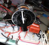
Today built up most circuits in this thread and settled on original Yamaha.
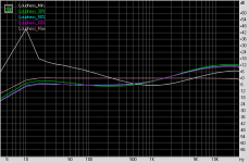
You would not think based on response plots.
But hooked up to a real amplifier sounded great.
I would say, even metaphysical.
Tweaked the input cap and resistor slightly but otherwise its the Yamaha circuit.
Best sound at various spl levels for me was between 5 and 6 on loudness dial.
You would not think based on response plots.
But hooked up to a real amplifier sounded great.
I would say, even metaphysical.
Tweaked the input cap and resistor slightly but otherwise its the Yamaha circuit.
Best sound at various spl levels for me was between 5 and 6 on loudness dial.
Attachments
Yep, this simple circuit sounds good.
What values did you settle to, and what load is it driving? Cause there are many "original Yamaha's" with different values.
What values did you settle to, and what load is it driving? Cause there are many "original Yamaha's" with different values.
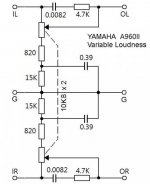
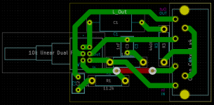
I used 10nF instead of the 8.2nF because can get 1% cheap.
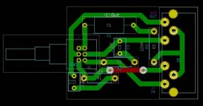
The series resistor waiting for final test 4.7k - 8.2k, doing new pcb.
All other values same.
In the final app it is driven with opa1622 headphone amp.
It requires very lo-z drive. Otherwise weird peaking responses.
The driven output load load on my test ckt is a 20kA volume pot .
It cannot be driven from typical line-out.
Attachments
Last edited:
Thus:
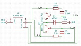
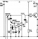
Guys, please help to find where is a mistake in the loudness control.
I used Alps RK09L series potmeter (100k log).
I think first mistake is that the potmeter wired reverse, according to the Freq. resp. measurement.
Questions:
- 10k log better instead of 100k log?
- Or I have to adjust the resistor size to 100k log?
Or there are another mistake?
Thanks
Laszlo
Attachments
Last edited:
Ok, first I replace 10k log type.
I just tested, and mesured with my Presonus AudioBox. Later I want to use with my tube amp. How should it be connected? Connect to the input siganal after the Volume pot.?
I just tested, and mesured with my Presonus AudioBox. Later I want to use with my tube amp. How should it be connected? Connect to the input siganal after the Volume pot.?
What specifically is the problem with it?
If presonus has a headphone out use that for drive as a test.
If presonus has a headphone out use that for drive as a test.
R1 and C2 must be connected to loudness tap, not to wiper.
Edit: this is not usual loudness circuit, bass eq is mono?
Strange, with potentiometer without loudness tap I would copy some old circuit from old amps/receivers that use this standard potentiometer.
But I never saw connection like this. Volume pots are always connected to ground, your is summed to mono and that connected to cap and resistor to ground.
Last edited:
One example of loudness with standard pot is on Pioneer SX700 receiver, but it has only bass boost.
What specifically is the problem with it?
If presonus has a headphone out use that for drive as a test.
I measured this freq. resp.
Attachments
R1 and C2 must be connected to loudness tap, not to wiper.
Edit: this is not usual loudness circuit, bass eq is mono?
Strange, with potentiometer without loudness tap I would copy some old circuit from old amps/receivers that use this standard potentiometer.
But I never saw connection like this. Volume pots are always connected to ground, your is summed to mono and that connected to cap and resistor to ground.
I followed a wrong schematic. I designed based on Loudness stage
instead of
Loudness stage
the R1 location is wrong.
I made a mistake too, sorry.
I was thinking that this is classic loudness on volume potentiometer, but this is Yamaha type of variable loudness, after the volume pot.
I was thinking that this is classic loudness on volume potentiometer, but this is Yamaha type of variable loudness, after the volume pot.
The loudness circuit like this must be drive by a low impedance circuit and not by a variable impedance circuit as it is the slider of a potentiometer.
I made a mistake too, sorry.
I was thinking that this is classic loudness on volume potentiometer, but this is Yamaha type of variable loudness, after the volume pot.
I changed the pot. from100k to 10k and according the original description I doubled the resistor values, and halve the capacitance, and it's working now. Thanks


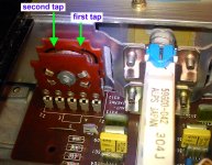
You're right, that pot is a special one, with two loudness taps.
Same as Grundig amplifiers, up to 1/3 is double loudness effect, from 1/3 to 2/3 is just one loudness, and after 2/3 is linear.
Same as Grundig amplifiers, up to 1/3 is double loudness effect, from 1/3 to 2/3 is just one loudness, and after 2/3 is linear.
- Home
- Source & Line
- Analog Line Level
- Loudness stage