Hi Tolu,
The external RS232 input accepts single character RS232 commands. The input consists of a LED with series resistor (opto-coupler). It can only accept commands and there is no handshaking.
Examples of external RS232 commands:
d decrease disk number
D increase disk number
t decrease track number
T increase track number
p play / pause
s stop
More commands will be added later, together with the gapless playback option.
It's possible to connect the RS232 to the main volume control unit that has a RS232 output, or connect it to a small module that translates infra-red codes into RS232 commands.
any information about remote control interface?
The external RS232 input accepts single character RS232 commands. The input consists of a LED with series resistor (opto-coupler). It can only accept commands and there is no handshaking.
Examples of external RS232 commands:
d decrease disk number
D increase disk number
t decrease track number
T increase track number
p play / pause
s stop
More commands will be added later, together with the gapless playback option.
It's possible to connect the RS232 to the main volume control unit that has a RS232 output, or connect it to a small module that translates infra-red codes into RS232 commands.
Hi maxlorenz,
The compact PCB lay-out with large ground plane was the only way to provide reproducable very high performance.
All electrolytic caps are indeed Rubycon ZL.
It will be very difficult to tweak...
The compact PCB lay-out with large ground plane was the only way to provide reproducable very high performance.
All electrolytic caps are indeed Rubycon ZL.
OK, the big question that no one has yet asked (but they're dying to know) - what's the pricing structure?
-ecdesigns- said:Hi Tolu,
The external RS232 input accepts single character RS232 commands. The input consists of a LED with series resistor (opto-coupler). It can only accept commands and there is no handshaking.
Examples of external RS232 commands:
d decrease disk number
D increase disk number
t decrease track number
T increase track number
p play / pause
s stop
More commands will be added later, together with the gapless playback option.
It's possible to connect the RS232 to the main volume control unit that has a RS232 output, or connect it to a small module that translates infra-red codes into RS232 commands.
Hi John,
very cool design!
It would be great if you could add a number function to select the disk and the track number via remote control. If you have a 32GB card you can choose between 70 disks. It isn't cool to push the button 70 times to get the last disk 😀 !
Origianlly posted by Tolu
It isn't cool to push the button 70 times to get the last disk
You simlpy can make the counter to advance progressively faster (up to a maximum), if you press the button for a full second or longer. This shouldn't be difficult to implement.
Kurt
Hi Tolu
This function will be one of the added RS232 commands.
It would be great if you could add a number function to select the disk and the track number via remote control. If you have a 32GB card you can choose between 70 disks. It isn't cool to push the button 70 times to get the last disk !
This function will be one of the added RS232 commands.
Hello -ecdesigns-
The following functions would make your SD-player a complete product.
A repeat function (track, CD, SD card),
and a random function (select random tracks)
that works both with repeat and without repeat.
Best regards,
Raymond
The following functions would make your SD-player a complete product.
A repeat function (track, CD, SD card),
and a random function (select random tracks)
that works both with repeat and without repeat.
Best regards,
Raymond
RayCtech said:Hello -ecdesigns-
The following functions would make your SD-player a complete product.
A repeat function (track, CD, SD card),
and a random function (select random tracks)
that works both with repeat and without repeat.
Best regards,
Raymond
I understand and agree that EC wants to include only a minimum of functions, at least in the first prototype. The present implementation, as far as I remember, has one button to step throgh the CDs and one button to step through the tracks. However, as I mentioned in an earlier post, these buttons should go to fast advance if pressed for a second or longer.
Kurt
Hi Javin5
There are 2 keys for increment / decrement Disk, the minus key can also toggle random disk function when readout is at 01. Random play is indicated by the decimal point. Playback stops when either key is pressed during playback.
There are 2 keys for increment / decrement Track, the minus key can also toggle random track function when readout is at 01. Random playback is indicated by the decimal point. Playback stops when either key is pressed during playback.
Then there is a stop key, and a play / pause key, so 6 in total.
Key repeat and gapless playback are also added now. Software efficiency was further improved.
By now I built a number of the redesigned PCBs for mainboard, SD-card module, and 3-crystal masterclock.
Modifications on the mainboard:
- Controller power supply decoupling pins were disconnected from 3V3 and decoupling capacitor value was increased.
- Traces from main controller to SD-card were made shorter in order to guarantee most reliable operation and minimize interference.
- Ground plane surface was slightly increased.
- Capacitors were placed on controller reset inputs.
- PCB outline was changed for easy front panel alignment.
Modifications on the SD-card PCB:
- PCB length was increased by 1mm for better fit in the standard housing.
- Pull-up resistor was added for card detect.
- SD-card illumination (for use under dim lighting conditions) was added.
Modifications 3-crystal master clock:
- PCB was re-designed for HC49 /4H crystals.
- Amplitude stabilization circuit was added.
- Power on the crystals was further reduced (oscillator now draws approx. 1 ... 2mA without load).
- Screen was added.
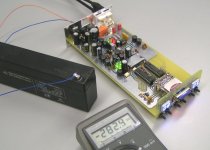
I also tested the SD-player on battery power supplies (12V lead-acid and 9V Alkaline D-cells), works fine, player draws approx. 280mA. I added a photograph of a SD-player running on a 12V / 2Ah lead-acid battery, the multimeter shows current consumption.
I understand and agree that EC wants to include only a minimum of functions, at least in the first prototype. The present implementation, as far as I remember, has one button to step through the CDs and one button to step throgh the tracks. However, as I mentioned in an earlier post, these buttons should go to fast advance if pressed for a second or longer.
There are 2 keys for increment / decrement Disk, the minus key can also toggle random disk function when readout is at 01. Random play is indicated by the decimal point. Playback stops when either key is pressed during playback.
There are 2 keys for increment / decrement Track, the minus key can also toggle random track function when readout is at 01. Random playback is indicated by the decimal point. Playback stops when either key is pressed during playback.
Then there is a stop key, and a play / pause key, so 6 in total.
Key repeat and gapless playback are also added now. Software efficiency was further improved.
By now I built a number of the redesigned PCBs for mainboard, SD-card module, and 3-crystal masterclock.
Modifications on the mainboard:
- Controller power supply decoupling pins were disconnected from 3V3 and decoupling capacitor value was increased.
- Traces from main controller to SD-card were made shorter in order to guarantee most reliable operation and minimize interference.
- Ground plane surface was slightly increased.
- Capacitors were placed on controller reset inputs.
- PCB outline was changed for easy front panel alignment.
Modifications on the SD-card PCB:
- PCB length was increased by 1mm for better fit in the standard housing.
- Pull-up resistor was added for card detect.
- SD-card illumination (for use under dim lighting conditions) was added.
Modifications 3-crystal master clock:
- PCB was re-designed for HC49 /4H crystals.
- Amplitude stabilization circuit was added.
- Power on the crystals was further reduced (oscillator now draws approx. 1 ... 2mA without load).
- Screen was added.
I also tested the SD-player on battery power supplies (12V lead-acid and 9V Alkaline D-cells), works fine, player draws approx. 280mA. I added a photograph of a SD-player running on a 12V / 2Ah lead-acid battery, the multimeter shows current consumption.
Attachments
Hello -ecdesigns-
I see from post #160 that you once considered using sonic resonators. Any other considerations regarding vibrations?
Do you think mechanical damping of the PCB would influence the sound?
(What about a single sided PCB which could be fitted to a piece of wood like "Altmann Attraction DAC"?)
Regards
I see from post #160 that you once considered using sonic resonators. Any other considerations regarding vibrations?
Do you think mechanical damping of the PCB would influence the sound?
(What about a single sided PCB which could be fitted to a piece of wood like "Altmann Attraction DAC"?)
Regards
Hi lor.e.s
The sonic resonators I refer to are omni-directional speakers (point source), the cones were part of the tweeter / midrange construction, but aluminum turned out to be unsuitable (poor sonic properties) for these parts. I now use either wood or acetal copolymer for these parts. I attached a photograph of this sonic resonator / speaker.
The SD-player is a semiconductor-memory based device, so all problems related to mechanical digital audio sources (CD, SACD, DVD, and Blu Ray) like resonances, CD pit / land induced jitter, servo noise, unwanted laser beam reflections, laser pick-up aging, read errors, and servo electronics interference, simply don't exist 🙂
The SD-player doesn't seem to be sensitive to resonances (no moving parts, carefully selected components).
The wood might have dielectric effects (PCB traces are pressed against the wood), but wood resonates too. It might also be just a good excuse to offer the DAC without housing 🙂
I see from post #160 that you once considered using sonic resonators. Any other considerations regarding vibrations?
Do you think mechanical damping of the PCB would influence the sound?
The sonic resonators I refer to are omni-directional speakers (point source), the cones were part of the tweeter / midrange construction, but aluminum turned out to be unsuitable (poor sonic properties) for these parts. I now use either wood or acetal copolymer for these parts. I attached a photograph of this sonic resonator / speaker.
The SD-player is a semiconductor-memory based device, so all problems related to mechanical digital audio sources (CD, SACD, DVD, and Blu Ray) like resonances, CD pit / land induced jitter, servo noise, unwanted laser beam reflections, laser pick-up aging, read errors, and servo electronics interference, simply don't exist 🙂
The SD-player doesn't seem to be sensitive to resonances (no moving parts, carefully selected components).
(What about a single sided PCB which could be fitted to a piece of wood like "Altmann Attraction DAC"?
The wood might have dielectric effects (PCB traces are pressed against the wood), but wood resonates too. It might also be just a good excuse to offer the DAC without housing 🙂
Attachments

Hello Ecdesigns / all;
i've been following this thread for some time now. I'm definitely interested in the device and cant' wait to purchase one.
My knowledge is rather limited and i think i may not have understood which kind of output-stage it uses...maybe someone can try and explain...?
Ecdesign, can you talk a little bit more about it's sound quality, because that would be quiet important to me.
Best regards,
Mickie
mickie said:
Ecdesign, can you talk a little bit more about it's sound quality, because that would be quiet important to me.
May I guess ?
The sound is crystal clear now.
Bernhard, your behaviour is unacceptable !
Stop spamming this thread
I reported this to the administrator.
Stop spamming this thread
I reported this to the administrator.
dddac said:Bernhard, your behaviour is unacceptable !
Stop spamming this thread
I reported this to the administrator.
That multiple posting was unintentional, browser or forum error, page did not load...
I hope you have not been hurt.
Hi ECdesig..
Congratulations for your result... idea, concept and prototype show high level of engineering... and technical skills also.
I'm pretty shure there are several, several, several guys waiting for your official offer of the player. I'm too.
But as someone plan to do, I intend to integrate your player to another DAC chip, maybe just buying the concept beyond your player...
Is that ok for you ? Can you offer just part of it, like the flashed microP, board and parts?
asking because I do not intend to offend your design property as we know you already has business at high end audio industry and this can turn into a product protected by rights...
I know it is a bit early to discuss this but it can contribute a lot to our community if one could have access to your product this way.
Thanks in advance and congrat again!
Hisatugo.🙂
Hi mickie,
SD-player sound quality can be compared with that heard in recording studios or at live performances. That was also my aim, and it seems I am getting close now.
The output stage consists of a 680 Ohm I/V resistor, and a 1uF coupling cap. The required 3V3 reference voltage for the passive I/V resistors is derived from a cascaded LED shunt regulator that's fed by a LED referenced discrete series regulator with integrated capacitance multiplier.
My knowledge is rather limited and i think i may not have understood which kind of output-stage it uses...maybe someone can try and explain...?
Ecdesign, can you talk a little bit more about it's sound quality, because that would be quiet important to me.
SD-player sound quality can be compared with that heard in recording studios or at live performances. That was also my aim, and it seems I am getting close now.
The output stage consists of a 680 Ohm I/V resistor, and a 1uF coupling cap. The required 3V3 reference voltage for the passive I/V resistors is derived from a cascaded LED shunt regulator that's fed by a LED referenced discrete series regulator with integrated capacitance multiplier.
- Status
- Not open for further replies.
- Home
- Source & Line
- Digital Source
- Lossless SD-card player