Very interesting! But I'm not sure if it's enough. I think the huge advantage of tube rectification for digital (properly implemented) is not only the soft switching, but it more or less creates a huge power source on it's own, which can instantly deliver whatever is needed, energy is delivered without delay, the energy does not have to be stored in capacitors. You have a cloud of electrons/energy waiting to be used (the field hardly changes).
With diode rectification capacitors need to fill huge gaps, with tube rectification capacitors only need to smoothen the ripples.
Capacitors are slow, they can not deliver the energy for a digital load which aggressively changes with 3MHz, thus creating jitter. To correct that afterwards, with such speed, seems nearly impossible to me.
Capacitors are even too slow for the normal audio signal in amplification as most big amplifiers struggle with a slow bass. Speed can be gained by using many smaller capacitors, but it will never approach the speed and abundance of energy you'll get with good tube rectification. Besides that linearity is poor, creating in harmonic distortions for the audio signal, resulting in a less natural, less rich sound. Both natural harmonics and rhythm (speed, dynamics) are the essence of (enjoying) music.
However, the evil factor in the power supply is not the regulator but the rectifier.
There are no worse than the C filterThe rectifier switching noise spectrum depends on, and is shaped by connected smoothing and decoupling caps. This is why each (electrolytic) cap causes different perceived sound quality, as it produces a different switching noise spectrum. The switching noise spectrum then inter-modulates with the signals processed by the connected circuits so the effects become audible.
use LC or RC filters after diodes and all will be ok.
for example mosfets+comparatorsProblem is there are no alternatives for the diodes
Capacitors are slow....
Hi Void,
that is a very general statement. Can you elaborate a bit more what exactly you mean with this and what real impact you see in audio applications?
thanks,
doede
A capacitor (or battery) can be seen as an RC delay, slow by definition.Hi Void,
that is a very general statement. Can you elaborate a bit more what exactly you mean with this and what real impact you see in audio applications?
thanks,
doede
Time constant = R x C (time to charge to 63% or discharge to 37%, in seconds)
Every part can be seen as an RC delay, but with a capacitor, C is very high and R is relatively high. By increasing capacity (f.i. placing capacitors in parallel), the internal impedance is lowered, however the external is not (loosing speed). However you need to charge/discharge less (gaining speed).
It's obvious that this has consequences for HF digital audio. For normal audio I don't understand if this has any consequences (i'm not an expert at all), but in practice it sounds like it does. Most power amplifiers either have a powerful, but slow bass (f.i. the typical slamming bass of a huge class-A solid state amp), or they have a fast bass kick but don't deliver the energy (f.i. opamp based amp with a small C). Power amplifiers which are both powerful and fast and also sound natural (harmonically correct) are very, very rare.
I've heard what's possible with a CD-player with a simple 1543 by Cees Pel, it's stunning. It has all the resolution, dynamics, flow, richness of the best analogue sources. He's worked on this for many years, using unconventional techniques, and he's still finding important improvements. Unfortunately he's not on the internet, he doesn't share much nowadays, and he's stopped selling his work, but the results can be heard on shows every now and then. If I see the work that's involved in his CD-transport (it's nearly impossible to reproduce this commercially), I'm very glad to see the SD as an alternative, in principle even better...
What happens to the sound when he switches back to a conventional power supply (diode and elco based) on the 1543, it just sounds like a very good 1543 again, but the loss in quality is just not an option (reduced richness, resolution, dynamics, more stress, etc.). His power supply is also not an option (very rare parts, extreme costs, etc.), so I guess some important work still needs to be done here.
But maybe John has made a very good PS already.
Last edited:
Hi void,
The basic principle of a tube rectifier is similar to a semiconductor rectifier. Both require a reservoir cap to "fill the gap" between charge cycles.
In both computers and cell phones, much higher frequencies are used, and decoupling is done with small capacitors. This seems to work quite well.
The power supply is highly critical for audio applications, one millivolt of ripple can already have disastrous effects on sound quality. Biggest problems in most power amps is the use of bipolar transistors, global feedback DC-servo's (Bass response), coupling caps, multiple power transistors / FETs in parallel, constant current sources (grain), current mirrors (very high grain), circuit complexity (instability), and filtering (input filter, Zobel network, transformers).
By now I tested the stepped rectifiers in both 5.4V power supply and bridge power amps. The results are stunning, especially for an "investment" of less than one euro on parts. I will use these stepped rectifiers in the ISD player for sure. The audible results are higher transparency, wider sound stage, and greatly enhanced trebles clarity. The effect is most clearly audible with high quality CD recordings like the ones from Stockfish Records for example.
Very interesting! But I'm not sure if it's enough. I think the huge advantage of tube rectification for digital (properly implemented) is not only the soft switching, but it more or less creates a huge power source on it's own, which can instantly deliver whatever is needed, energy is delivered without delay, the energy does not have to be stored in capacitors. You have a cloud of electrons/energy waiting to be used (the field hardly changes).
With diode rectification capacitors need to fill huge gaps, with tube rectification capacitors only need to smoothen the ripples.
The basic principle of a tube rectifier is similar to a semiconductor rectifier. Both require a reservoir cap to "fill the gap" between charge cycles.
Capacitors are slow, they can not deliver the energy for a digital load which aggressively changes with 3MHz, thus creating jitter. To correct that afterwards, with such speed, seems nearly impossible to me.
In both computers and cell phones, much higher frequencies are used, and decoupling is done with small capacitors. This seems to work quite well.
Capacitors are even too slow for the normal audio signal in amplification as most big amplifiers struggle with a slow bass. Speed can be gained by using many smaller capacitors, but it will never approach the speed and abundance of energy you'll get with good tube rectification. Besides that linearity is poor, creating in harmonic distortions for the audio signal, resulting in a less natural, less rich sound. Both natural harmonics and rhythm (speed, dynamics) are the essence of (enjoying) music.
The power supply is highly critical for audio applications, one millivolt of ripple can already have disastrous effects on sound quality. Biggest problems in most power amps is the use of bipolar transistors, global feedback DC-servo's (Bass response), coupling caps, multiple power transistors / FETs in parallel, constant current sources (grain), current mirrors (very high grain), circuit complexity (instability), and filtering (input filter, Zobel network, transformers).
By now I tested the stepped rectifiers in both 5.4V power supply and bridge power amps. The results are stunning, especially for an "investment" of less than one euro on parts. I will use these stepped rectifiers in the ISD player for sure. The audible results are higher transparency, wider sound stage, and greatly enhanced trebles clarity. The effect is most clearly audible with high quality CD recordings like the ones from Stockfish Records for example.
ISD player project progress,
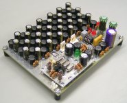
Next module (TDA1543 DAC module) has been completed and tested. This module is intended for the basic ISD player.
First picture shows the component side. There is an un-interrupted ground plane used here. The cluster of capacitors and chokes on the top form 3 separate 20th order LC filters. These are fed by the 5.4V power supply and are used to filter super clock and passive I/V resistor reference voltages for L and R channels.
The superclock module (bottom) requires some screening, I will add that later. The 2-way connector of the left outputs 11.2896 Mhz for the SD-transport. The connector close to the superclock is for the I2S interface. BCK is reclocked by the superclock and fed to the TDA1543 using a dynamic jitter attenuator circuit. The remaining I2S signals (WS / DATA) are fed to the TDA1543 using I2S attenuators. The red LEDs are part of the shunt regulators that provide L and R channel reference voltages. The passive non-inductive I/V resistors are high wattage wire wound types (constantine wire) with low self capacitance, using a mobius / honeycomb winding pattern. The TDA1543 is a selected (lowest THD) cryo-treated version. Advantages over TDA1541A are single power supply, no DEM clock and associated "issues", ability to generate suitable ac voltages directly across a passive I/V resistor without the need for active amplification, and low on-chip interference due to simple straight-forward circuit.
The coupling caps (only ones in the entire signal path) will be either hybrids, V-cap TFTF or Duelund VSF copper foil (if these are still available). I am waiting for over 2 months on the Duelund caps I payed in advance, still haven't received any yet.
Second photo shows the solder side. Only few components, the blue Schottky diodes are part of the dynamic jitter attenuator.
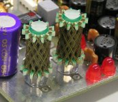
Third photograph shows the 700 Ohm passive I/V resistors in detail. These offered best performance by far, easily outperforming Rhopoint, Vishay bulk metal foil, and other audiophile resistors. Key factors are extreme low noise (high-wattage wire wound), non-inductive design, and low self capacitance.
The only downside is that it takes many hours, steel nerves, steady hand, special techniques (tension) and patience to wind these. The trick is to prevent exact alignment of the wires in order to further decrease self capacitance. This is controlled by varying the exact wire tension during winding.
The photograph shows the size of these resistors in comparison with 5mm LEDs.
Final module to design is the 5.4V power supply module. I plan to use a new regulator concept here that also compensates for load back emf. Conventional series regs cannot correct (peak) voltages generated by the load. The series transistor can only switch-off while the back emf voltage will then increase the regulated voltage, depending on decoupling capacitor specs.
Shunt regs cannot correct voltage dips (surge currents) drawn by the load as they have to be fed by limited current. So I plan to design a regulator that can do both. This regulator will have an output stage similar to a power amp, using a complementary pair.
Next module (TDA1543 DAC module) has been completed and tested. This module is intended for the basic ISD player.
First picture shows the component side. There is an un-interrupted ground plane used here. The cluster of capacitors and chokes on the top form 3 separate 20th order LC filters. These are fed by the 5.4V power supply and are used to filter super clock and passive I/V resistor reference voltages for L and R channels.
The superclock module (bottom) requires some screening, I will add that later. The 2-way connector of the left outputs 11.2896 Mhz for the SD-transport. The connector close to the superclock is for the I2S interface. BCK is reclocked by the superclock and fed to the TDA1543 using a dynamic jitter attenuator circuit. The remaining I2S signals (WS / DATA) are fed to the TDA1543 using I2S attenuators. The red LEDs are part of the shunt regulators that provide L and R channel reference voltages. The passive non-inductive I/V resistors are high wattage wire wound types (constantine wire) with low self capacitance, using a mobius / honeycomb winding pattern. The TDA1543 is a selected (lowest THD) cryo-treated version. Advantages over TDA1541A are single power supply, no DEM clock and associated "issues", ability to generate suitable ac voltages directly across a passive I/V resistor without the need for active amplification, and low on-chip interference due to simple straight-forward circuit.
The coupling caps (only ones in the entire signal path) will be either hybrids, V-cap TFTF or Duelund VSF copper foil (if these are still available). I am waiting for over 2 months on the Duelund caps I payed in advance, still haven't received any yet.
Second photo shows the solder side. Only few components, the blue Schottky diodes are part of the dynamic jitter attenuator.
Third photograph shows the 700 Ohm passive I/V resistors in detail. These offered best performance by far, easily outperforming Rhopoint, Vishay bulk metal foil, and other audiophile resistors. Key factors are extreme low noise (high-wattage wire wound), non-inductive design, and low self capacitance.
The only downside is that it takes many hours, steel nerves, steady hand, special techniques (tension) and patience to wind these. The trick is to prevent exact alignment of the wires in order to further decrease self capacitance. This is controlled by varying the exact wire tension during winding.
The photograph shows the size of these resistors in comparison with 5mm LEDs.
Final module to design is the 5.4V power supply module. I plan to use a new regulator concept here that also compensates for load back emf. Conventional series regs cannot correct (peak) voltages generated by the load. The series transistor can only switch-off while the back emf voltage will then increase the regulated voltage, depending on decoupling capacitor specs.
Shunt regs cannot correct voltage dips (surge currents) drawn by the load as they have to be fed by limited current. So I plan to design a regulator that can do both. This regulator will have an output stage similar to a power amp, using a complementary pair.
Attachments

Hi EC -
This all looks fantastic, but are ordinary mortals going to be able to afford it now? The cost will presumably be way beyond your estimates for the original version.
This all looks fantastic, but are ordinary mortals going to be able to afford it now? The cost will presumably be way beyond your estimates for the original version.
ISD player update,
ISD prototype almost ready, only 5.4V main power supply module PCB still has to be designed. Same applies to the top and rear panels.
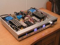
I attached a photograph of the ISD prototype in action.
The modules on left and right are the DC-coupled high resolution FET bridge power amps, power is limited by 25VA toroidal transformers because of very high SR60 efficiency. Each mono block has 8 FETs, two dual JFETs and 4 matched power MOSFETs in the unity gain bridge output stage. The amps do not have global feedback nor any filtering, current sources are replaced by hybrid chokes in series with a resistor. It is used in balanced mode (power amps have both balanced in and outputs). The DAC chip ground is connected using Kelvin coupling, eliminating residual GND interference by sensing on DAC AGND pin.
At normal to high volume settings the complete unit consumes average of 25 watts, power amplifiers included. Most power (20 watts) is consumed by bridge output stage bias current. There are 3 separate mains connections, one for each mono block and one for the 5.4V logic power supply. The logic circuits can also be powered by an external 12V battery.
The ISD player remains in stand by after "switching-off", so there is no warm-up / settling time when the unit is switched-on. This way the unit offers instant maximum performance after switching-on.
Wiring is home-made litz wire with PTFE insulation. Analogue interlinks are all hard-wired, directly between PCBs. Common ground plane for all analogue modules is formed by the 3mm thick solid aluminum bottom plate.
The module in the center is the TDA1543 DAC module with on-board 11.2896 MHz superclock / reclocker module. I/V resistors are wire wound mobius / honeycomb versions.
The "modules" on the left and right of the DAC module are home made 3.3uF / 250V high resolution hybrid capacitors that easily outperformed V-cap TFTF that I used as reference.
I still plan to test Duelund VSF copper foil caps when I receive them, but for now the hybrids are excellent.
bottom right module contains a motorized ALPS pot plus input selection and muting relays.
System control module and SD-transport are mounted on the front panel frame that also forms a screened compartment for both modules.
The volume knob from massive aluminum is home made, it also contains an indicator LED. Connection is made through a spring-loaded test pin and a circular PCB integrated in the knob.
The unit can be operated manually (front panel keys) or by a remote control.
To answer jonner's question, this ISD player is probably the cheapest solution for high performance CD playback. The SD-transport module will cost eur 199 (VAT exclusive), you probably won't get a brand new CDPROII plus display / keyboard module for that, and I think it's safe to say that the SD-transport concept is better compared to an audiophile CD transport.
The other modules can be offered at reasonable price too, and don't forget that what you are looking at is a complete audio set, not just a SD-transport or DAC. All you need to add is a set of speakers.
ISD prototype almost ready, only 5.4V main power supply module PCB still has to be designed. Same applies to the top and rear panels.
I attached a photograph of the ISD prototype in action.
The modules on left and right are the DC-coupled high resolution FET bridge power amps, power is limited by 25VA toroidal transformers because of very high SR60 efficiency. Each mono block has 8 FETs, two dual JFETs and 4 matched power MOSFETs in the unity gain bridge output stage. The amps do not have global feedback nor any filtering, current sources are replaced by hybrid chokes in series with a resistor. It is used in balanced mode (power amps have both balanced in and outputs). The DAC chip ground is connected using Kelvin coupling, eliminating residual GND interference by sensing on DAC AGND pin.
At normal to high volume settings the complete unit consumes average of 25 watts, power amplifiers included. Most power (20 watts) is consumed by bridge output stage bias current. There are 3 separate mains connections, one for each mono block and one for the 5.4V logic power supply. The logic circuits can also be powered by an external 12V battery.
The ISD player remains in stand by after "switching-off", so there is no warm-up / settling time when the unit is switched-on. This way the unit offers instant maximum performance after switching-on.
Wiring is home-made litz wire with PTFE insulation. Analogue interlinks are all hard-wired, directly between PCBs. Common ground plane for all analogue modules is formed by the 3mm thick solid aluminum bottom plate.
The module in the center is the TDA1543 DAC module with on-board 11.2896 MHz superclock / reclocker module. I/V resistors are wire wound mobius / honeycomb versions.
The "modules" on the left and right of the DAC module are home made 3.3uF / 250V high resolution hybrid capacitors that easily outperformed V-cap TFTF that I used as reference.
I still plan to test Duelund VSF copper foil caps when I receive them, but for now the hybrids are excellent.
bottom right module contains a motorized ALPS pot plus input selection and muting relays.
System control module and SD-transport are mounted on the front panel frame that also forms a screened compartment for both modules.
The volume knob from massive aluminum is home made, it also contains an indicator LED. Connection is made through a spring-loaded test pin and a circular PCB integrated in the knob.
The unit can be operated manually (front panel keys) or by a remote control.
To answer jonner's question, this ISD player is probably the cheapest solution for high performance CD playback. The SD-transport module will cost eur 199 (VAT exclusive), you probably won't get a brand new CDPROII plus display / keyboard module for that, and I think it's safe to say that the SD-transport concept is better compared to an audiophile CD transport.
The other modules can be offered at reasonable price too, and don't forget that what you are looking at is a complete audio set, not just a SD-transport or DAC. All you need to add is a set of speakers.
Attachments

Holly, you made you own caps... I've first seen the pictures and looking at those strange structures flanking the module I was like: Don't tell me...
Well, it's safe to say I have never seen something like this before. Ever!
You are an inspiration. I thank you for this!
By the way. If you'll ever get the time, motivation to do this and it doesn't affect your business. Do you think it's possible to see some articles written by you on "home made inductors, home made capacitors" or, I don't know, "The clearest Path - A guide to digital Power Supply designs." This would be legacy! 🙂
John.
What's missing is your own DAC! 😉
BTW:
You might consider a 2nd DAC output to drive a pair of stereo subs. ( I do it in my current setup via a Behringer. The Behringer and the amp input are hooked up in parallel. Perhaps this could be done with an output-transformer.
Cheers
What's missing is your own DAC! 😉
BTW:
You might consider a 2nd DAC output to drive a pair of stereo subs. ( I do it in my current setup via a Behringer. The Behringer and the amp input are hooked up in parallel. Perhaps this could be done with an output-transformer.
Cheers
EC -
Glad to hear that the costs are still likely to be reasonable. 😎
On the issue of the pot, I'm just wondering if you have tried revisiting the optocoupler attenuator solution since you improved your speakers and power amp?
I used to think that the opto route was inferior, but since I've improved the HF balance of my speakers I now think I was wrong.
Hi nicoch46,
This depends on the application. In the ISD player it works fine.
ALPS pot ? is not so good....
This depends on the application. In the ISD player it works fine.
Potentiometer
Does it control relays in a variable gain?
Hi nicoch46,
This depends on the application. In the ISD player it works fine.
Does it control relays in a variable gain?
 ecd my mistake
Hi jgazal,
No, signal path looks like this:
I/V resistor > coupling cap > ALPS pot > bridge power amp > speakers.
Signal path is kept as simple as possible with fewest components in the signal path.
The reason the ALPS pot works fine in the ISD player is because of short, hard wired litz wire interlinks, and use of a very high resolution DC-coupled bridge power amp.
ISD player is now almost completed. The attached picture shows the ISD player being tested.
The 5.4V power supply is now ready (center rear). It powers syscon, DAC, and SD-transport modules.
I also installed 2-stage stepped rectifier modules on the bridge power amps (5 x dual fast, slow recovery diodes in TO-220 housing).
On the rear there are 3 mains connections to power each subsection, one power switch, DC socket for battery operation, 2 speaker connections, and 2 external analogue stereo inputs.
Does it control relays in a variable gain?
No, signal path looks like this:
I/V resistor > coupling cap > ALPS pot > bridge power amp > speakers.
Signal path is kept as simple as possible with fewest components in the signal path.
The reason the ALPS pot works fine in the ISD player is because of short, hard wired litz wire interlinks, and use of a very high resolution DC-coupled bridge power amp.
ISD player is now almost completed. The attached picture shows the ISD player being tested.
The 5.4V power supply is now ready (center rear). It powers syscon, DAC, and SD-transport modules.
I also installed 2-stage stepped rectifier modules on the bridge power amps (5 x dual fast, slow recovery diodes in TO-220 housing).
On the rear there are 3 mains connections to power each subsection, one power switch, DC socket for battery operation, 2 speaker connections, and 2 external analogue stereo inputs.
Attachments
dear john,
the isd player looks really great!
please excuse my ignorance, i do not understand why the alp poti should reveal in your configuration the same good results as the known nice resistor-attenuators, lightspeed, tvc, etc. i thought because the resolution of the amp is high then you will need an excellent pre-stage as well to ensure this high resolution. or this is more relaxed because of the nature of dc-coupling to the power-amp?
i would like also to repeat the klaus’s (soundcheck) request for 2nd stereo subwoofer outputs after the dac. many of us use active subs that should to be connected through low-level inputs.
another question: do you have still enough room in the cabinet to include a tube output stage?
can some parts of your dac basic-module(1543) be kept if you introduce 1541 or 1865 modules in the future? or it has to be a total new design?
now your prototype seems to be complete. have you any price estimation for each modules? 🙂 you see i am very keen to get one of the first devices (if i can afford it ;-) ) .
many thanks
kind regards
mamal
Hi mr_whocares,
The ISD player is a unique concept as it combines all audio components in one housing and uses a virtually perfect digital audio source. This greatly reduces problems that would arise with separate audio components connected through conventional interlinks using sockets and plugs. One side effect is that the volume pot is less critical now, and an ALPS pot really functions very well with this specific concept. Alternative could be a TKD 2CP-2511MC Motorized stereo volume control:
TKD Tokyo Ko-On Denpa volume controls main page
I already tried other options like the lightspeed attenuator and relay volume control using bulk metal foil resistors, but these failed to improve on plain potentiometers with this application.
I have to add that the ISD player uses large bandwidth signal processing all the way up to the speaker outputs. The matching speakers (SR60) are also optimized to handle large bandwidth signals (passive crossover filter) by using very high speed hybrid caps and multi-segmented honeycomb air chokes wound with litz wire.
This conflicts with ISD player concept, and would lead to sound quality degradation. Reasons for this, a ground loop is introduced by connecting an external active circuit, the amount of components in the signal path is at least doubled, and it's virtually impossible to get both main speakers and separate active sub act as a unity.
It would also require an active buffer between I/V resistor and active sub, further degrading sound quality. Finally external interference would be routed back to the I/V resistor, causing even more problems (even buffer amps pass interference).
Yes there is enough room, I could even mount the tube(s) inside the housing so it remains very compact. Problem however, the ISD player will reveal typical tube distortion without mercy, this can be a good thing if you like "tube sound", but it's not desired if you prefer utmost transparency and refinement.
When swapping DACs, both DAC module and power supply have to be swapped. The superclock (that must be mounted on the DAC module) can be re-used. Some DAC chips like the AD1865 need extensive glue logic that make it extremely difficult to maintain low noise I2S signals. Common belief is that only the I2S timing signal needs to have low jitter, and that jitter on all I2S signals can be easily removed by reclocking. In practice, the only way to get really clean I2S signals is to use brickwall bandpass filters with less than 10Hz bandwidth in order to suppress source jitter spectrum. The DATA signal however requires larger bandwidth, making effective brickwall bandpass filtering very difficult. Note that all I2S interference (jitter) ends up and inter modulates with audio spectrum and reflected mirror images. This is one of the reasons that no two digital audio sources sound the same.
This is why I had to develop the SD-transport, here the generated I2S stream is already very clean (before reclocking) something that's seldom the case with any other digital audio source. Since I run both source and DAC from one single master clock, I only have one clock jitter spectrum. If I would use multiple clocks (ASRC, PLL, asynchronous reclocker, tracker), I would end up with inter modulation products of both clocks, adding a lot of extra interference that cannot be removed.
Currently available modules and prices (VAT exclusive):
SD-transport with removable SD-card holder module : eur 199
TDA1543 DAC module without superclock and wire wound Mobius / honeycomb I/V resistors : eur 150
Superclock (11.2906 MHz) : eur 75
Handcrafted 700 Ohm wire wound mobius / honeycomb I/V resistors : eur 50 each
Both modules and and PCBs are fully handcrafted and tested. I also offer these modules built on HF PCB material. I compared these with epoxy PCBs, and in the ISD player I noticed higher refinement when using HF PCBs for syscon module, SD-transport, DAC module and superclock. All these modules generate / use high frequencies and are built rather compact (SMD), so here HF PCB material could offer advantages. The HF PCB material also offers better mechanical properties (less bending, better heat resistance).
When constructing a player / DAC combination only, using these modules, price will be comparable with the first SD-player project. However performance of the new SD player project is much better.
Rest of the modules and ISD player housing will become available soon.
The modules can be used for own projects or for constructing a complete ISD player.
please excuse my ignorance, i do not understand why the alp poti should reveal in your configuration the same good results as the known nice resistor-attenuators, lightspeed, tvc, etc. i thought because the resolution of the amp is high then you will need an excellent pre-stage as well to ensure this high resolution.
The ISD player is a unique concept as it combines all audio components in one housing and uses a virtually perfect digital audio source. This greatly reduces problems that would arise with separate audio components connected through conventional interlinks using sockets and plugs. One side effect is that the volume pot is less critical now, and an ALPS pot really functions very well with this specific concept. Alternative could be a TKD 2CP-2511MC Motorized stereo volume control:
TKD Tokyo Ko-On Denpa volume controls main page
I already tried other options like the lightspeed attenuator and relay volume control using bulk metal foil resistors, but these failed to improve on plain potentiometers with this application.
I have to add that the ISD player uses large bandwidth signal processing all the way up to the speaker outputs. The matching speakers (SR60) are also optimized to handle large bandwidth signals (passive crossover filter) by using very high speed hybrid caps and multi-segmented honeycomb air chokes wound with litz wire.
i would like also to repeat the klaus’s (soundcheck) request for 2nd stereo subwoofer outputs after the dac. many of us use active subs that should to be connected through low-level inputs.
This conflicts with ISD player concept, and would lead to sound quality degradation. Reasons for this, a ground loop is introduced by connecting an external active circuit, the amount of components in the signal path is at least doubled, and it's virtually impossible to get both main speakers and separate active sub act as a unity.
It would also require an active buffer between I/V resistor and active sub, further degrading sound quality. Finally external interference would be routed back to the I/V resistor, causing even more problems (even buffer amps pass interference).
another question: do you have still enough room in the cabinet to include a tube output stage?
Yes there is enough room, I could even mount the tube(s) inside the housing so it remains very compact. Problem however, the ISD player will reveal typical tube distortion without mercy, this can be a good thing if you like "tube sound", but it's not desired if you prefer utmost transparency and refinement.
can some parts of your dac basic-module(1543) be kept if you introduce 1541 or 1865 modules in the future? or it has to be a total new design?
When swapping DACs, both DAC module and power supply have to be swapped. The superclock (that must be mounted on the DAC module) can be re-used. Some DAC chips like the AD1865 need extensive glue logic that make it extremely difficult to maintain low noise I2S signals. Common belief is that only the I2S timing signal needs to have low jitter, and that jitter on all I2S signals can be easily removed by reclocking. In practice, the only way to get really clean I2S signals is to use brickwall bandpass filters with less than 10Hz bandwidth in order to suppress source jitter spectrum. The DATA signal however requires larger bandwidth, making effective brickwall bandpass filtering very difficult. Note that all I2S interference (jitter) ends up and inter modulates with audio spectrum and reflected mirror images. This is one of the reasons that no two digital audio sources sound the same.
This is why I had to develop the SD-transport, here the generated I2S stream is already very clean (before reclocking) something that's seldom the case with any other digital audio source. Since I run both source and DAC from one single master clock, I only have one clock jitter spectrum. If I would use multiple clocks (ASRC, PLL, asynchronous reclocker, tracker), I would end up with inter modulation products of both clocks, adding a lot of extra interference that cannot be removed.
now your prototype seems to be complete. have you any price estimation for each modules? 🙂 you see i am very keen to get one of the first devices (if i can afford it ;-) ) .
Currently available modules and prices (VAT exclusive):
SD-transport with removable SD-card holder module : eur 199
TDA1543 DAC module without superclock and wire wound Mobius / honeycomb I/V resistors : eur 150
Superclock (11.2906 MHz) : eur 75
Handcrafted 700 Ohm wire wound mobius / honeycomb I/V resistors : eur 50 each
Both modules and and PCBs are fully handcrafted and tested. I also offer these modules built on HF PCB material. I compared these with epoxy PCBs, and in the ISD player I noticed higher refinement when using HF PCBs for syscon module, SD-transport, DAC module and superclock. All these modules generate / use high frequencies and are built rather compact (SMD), so here HF PCB material could offer advantages. The HF PCB material also offers better mechanical properties (less bending, better heat resistance).
When constructing a player / DAC combination only, using these modules, price will be comparable with the first SD-player project. However performance of the new SD player project is much better.
Rest of the modules and ISD player housing will become available soon.
The modules can be used for own projects or for constructing a complete ISD player.
- Status
- Not open for further replies.
- Home
- Source & Line
- Digital Source
- Lossless SD-card player