EC.
Impressive work again. Looks like art.
I guess there won't be much space left for a "mkII" once you're finished. 😀
What I heard last time at your place was pretty good already. Interesting to see that there
is still some air left
The 1541 was obviously delivering more details last time. I guess now you'll be much closer to a 1541 - aren't you?
Christmas is coming soon. Lets hope that you`ll get the first batch finished prior to the holidays. 😉
Cheers
Dear EC,
Thank you for you detailed explanation about the construction method.
I plan to test first inductors and low value power resistors, to use on my SS Class A amps. I will use ceramic or clay to deal with the heat. Maybe you have some ideas on that subject?
Thank you for you detailed explanation about the construction method.
I plan to test first inductors and low value power resistors, to use on my SS Class A amps. I will use ceramic or clay to deal with the heat. Maybe you have some ideas on that subject?
Hi soundcheck,
There is plenty of air left, the set was not yet optimized for high resolution.
The new SR60 speakers made a world of difference, and there is probably even some more room for improvement (I ordered some Duelund VSF copper foil capacitors to test in the passive crossover filter).
Duelund Coherent Audio
The DC-coupled zero global feedback bridge power amp was improved by increasing total smoothing capacitance to 30,000uF, and adding extra power supply filters on both differential input and differential drive circuits.
This revealed much more information, so the SD-player performance had to be further improved too.
Starting with the 3-crystal master clock, the circuit was completely redesigned in order to achieve much better PSRR (improvement up to factor 50), and very high load immunity (less than 0.02 Hz / pF frequency shift) this translates to an additional improvement of up to factor 40.
Clock injection was changed too, the processor connects to the buffered output, the synchronous reclocker was coupled to the extreme low distortion 10Vpp sinewave output (filtered by 3 crystals that are also used for oscillation). The coupling is made through approx. 0.25pF home-made TFTF cap. The reclocker clock input is connected to a 2V reference voltage. The trigger window dynamically tracks the clock signal average DC level. This way highly accurate triggering is obtained.
The power supplies were improved too, there is one discrete 5V series regulator using 2 bipolar low noise transistors. All other voltage regulators are passive in order to achieve fastest possible response time (zero feedback). They consist of (cascaded) filtered LED shunt regulators (The already low LED noise is attenuated using passive LC filters).
LC filter was added to the display power supply (segment driver) to minimize noise levels when the display is switched-on. When the display is turned off (key) display noise is non existent.
Vref for the passive I/V resistors was split-up in order to achieve better channel separation.
All critical GND connections were made using 4mm diameter litz wire consisting of 128 insulated strands. This way very low impedance was realized between critical circuits. Such low impedance couldn't be realized easily using ground planes.
The I/V resistors are non-inductive high wattage (30 watts) wirewound mobius / honeycomb versions that offer very high resolution.
The coupling caps were bypassed by home-made solid capacitors that consist of two copper foils that are fused to a 0.5mm thick dieelectricum (1.5nF). The big advantage of these decoupling caps is that they don't resonate like conventional foil caps, so they provide excellent resonance suppression of the 3.3uF foil coupling caps. I also plan to test Duelund VSF copper foil caps.
The Duelund VSF (Virtual Stacked Foil) caps are interesting because they use stacked copper foil and impregnated high density paper. This could offer very low mechanical resonances. Most conventional capacitors resonate at multiple frequencies. Just hook them up to a function generator and apply a 20Vpp sinewave (within the audio range) and you can actually hear the capacitors making audible noise. This means that the foil inside can still move, so the capacitor will suffer from piezoelectric affects that cause sound coloration. These resonances are likely to extend into the ultrasonic range.
This could very well explain the "burn in" effect that basically equalizes the tension of the foil by driving audio signals through them that will make the foil resonate and settle after a while. The settled foil will still resonate, but the spectrum will be different from a new unused cap.
I have reason to believe that sonic differences between capacitors are mainly caused by mechanical resonances of the foil rather than dielectric properties. So foils that offer best damping are likely to offer best sonic performance. plastic dieelectricums usually offer poor damping (very light and flexible). Impregnated paper offers better damping.
Other critical part is the connection of the leads to the foil, connections to metalized plastics are usually of poor quality. Leads directly soldered or welded to copper foil offer much better connections. The leads can also guide external mechanical resonances into the capacitor, so it's best to use flexible (litz) wire connections and mount the capacitors in such way that mechanical resonances are reduced.
The circuits weren't optimal then, and the TDA1543 performed better when running on a battery power supply. Now the TDA1543 performs virtually identical on mains power supplies as a result of recent modifications.
I repeated the comparison with optimized SD-player, modified bridge amps and new SR60 speakers. Now the differences are only marginal and only audible by direct comparison and it's rather a question of taste what DAC chip to choose.
The TDA1541A DAC has I2S attenuators, DJA, latest DEM clock injector (diode-resistor), discrete series regulator supplies with filtered LED reference, and full passive I/V conversion (140 Ohm non-inductive wirewound mobius / honeycomb resistor) offering up to 550mVpp straight from the TDA1541A output without any active devices. I used a 3mA bias current (resistor + hybrid choke) for maintaining low THD (output compliance) at these output levels.
I still plan to design a TDA1541A-based SD-player when I have time for it.
What I heard last time at your place was pretty good already. Interesting to see that there
is still some air left
There is plenty of air left, the set was not yet optimized for high resolution.
The new SR60 speakers made a world of difference, and there is probably even some more room for improvement (I ordered some Duelund VSF copper foil capacitors to test in the passive crossover filter).
Duelund Coherent Audio
The DC-coupled zero global feedback bridge power amp was improved by increasing total smoothing capacitance to 30,000uF, and adding extra power supply filters on both differential input and differential drive circuits.
This revealed much more information, so the SD-player performance had to be further improved too.
Starting with the 3-crystal master clock, the circuit was completely redesigned in order to achieve much better PSRR (improvement up to factor 50), and very high load immunity (less than 0.02 Hz / pF frequency shift) this translates to an additional improvement of up to factor 40.
Clock injection was changed too, the processor connects to the buffered output, the synchronous reclocker was coupled to the extreme low distortion 10Vpp sinewave output (filtered by 3 crystals that are also used for oscillation). The coupling is made through approx. 0.25pF home-made TFTF cap. The reclocker clock input is connected to a 2V reference voltage. The trigger window dynamically tracks the clock signal average DC level. This way highly accurate triggering is obtained.
The power supplies were improved too, there is one discrete 5V series regulator using 2 bipolar low noise transistors. All other voltage regulators are passive in order to achieve fastest possible response time (zero feedback). They consist of (cascaded) filtered LED shunt regulators (The already low LED noise is attenuated using passive LC filters).
LC filter was added to the display power supply (segment driver) to minimize noise levels when the display is switched-on. When the display is turned off (key) display noise is non existent.
Vref for the passive I/V resistors was split-up in order to achieve better channel separation.
All critical GND connections were made using 4mm diameter litz wire consisting of 128 insulated strands. This way very low impedance was realized between critical circuits. Such low impedance couldn't be realized easily using ground planes.
The I/V resistors are non-inductive high wattage (30 watts) wirewound mobius / honeycomb versions that offer very high resolution.
The coupling caps were bypassed by home-made solid capacitors that consist of two copper foils that are fused to a 0.5mm thick dieelectricum (1.5nF). The big advantage of these decoupling caps is that they don't resonate like conventional foil caps, so they provide excellent resonance suppression of the 3.3uF foil coupling caps. I also plan to test Duelund VSF copper foil caps.
The Duelund VSF (Virtual Stacked Foil) caps are interesting because they use stacked copper foil and impregnated high density paper. This could offer very low mechanical resonances. Most conventional capacitors resonate at multiple frequencies. Just hook them up to a function generator and apply a 20Vpp sinewave (within the audio range) and you can actually hear the capacitors making audible noise. This means that the foil inside can still move, so the capacitor will suffer from piezoelectric affects that cause sound coloration. These resonances are likely to extend into the ultrasonic range.
This could very well explain the "burn in" effect that basically equalizes the tension of the foil by driving audio signals through them that will make the foil resonate and settle after a while. The settled foil will still resonate, but the spectrum will be different from a new unused cap.
I have reason to believe that sonic differences between capacitors are mainly caused by mechanical resonances of the foil rather than dielectric properties. So foils that offer best damping are likely to offer best sonic performance. plastic dieelectricums usually offer poor damping (very light and flexible). Impregnated paper offers better damping.
Other critical part is the connection of the leads to the foil, connections to metalized plastics are usually of poor quality. Leads directly soldered or welded to copper foil offer much better connections. The leads can also guide external mechanical resonances into the capacitor, so it's best to use flexible (litz) wire connections and mount the capacitors in such way that mechanical resonances are reduced.
The 1541 was obviously delivering more details last time
The circuits weren't optimal then, and the TDA1543 performed better when running on a battery power supply. Now the TDA1543 performs virtually identical on mains power supplies as a result of recent modifications.
I repeated the comparison with optimized SD-player, modified bridge amps and new SR60 speakers. Now the differences are only marginal and only audible by direct comparison and it's rather a question of taste what DAC chip to choose.
The TDA1541A DAC has I2S attenuators, DJA, latest DEM clock injector (diode-resistor), discrete series regulator supplies with filtered LED reference, and full passive I/V conversion (140 Ohm non-inductive wirewound mobius / honeycomb resistor) offering up to 550mVpp straight from the TDA1541A output without any active devices. I used a 3mA bias current (resistor + hybrid choke) for maintaining low THD (output compliance) at these output levels.
I still plan to design a TDA1541A-based SD-player when I have time for it.
Yhe, but does it sound any better, ;-)
Sound can be interpreted in many ways. I want to be more specific.
The ideal would be reproducing sound quality experienced at live performances. This is and has always been my major objective.
This doesn't mean impressive sound, but simply reproducing sound as realistic as possible, given the practical limitations of electronic circuits. This turned out to be much more problematic than expected.
The higher sound quality gets (detail, transparency smoothness, transient response) the more difficult it will get to correct the final flaws. Cleaner sound also clearly reveals the existing flaws that remained inaudible (masked) before.
That's why I spent so much time systematically tuning both the SD-player and audio set, and was even forced to produce some home-made parts like the honeycomb resistors, chokes and the bypass caps.
I always use multiple references in order to make absolutely sure a modification indeed improves performance (this isn't always the case). I also have a number of people who verify tuning results, this is necessary to get a more objective opinion, among these people are some musicians. I also use high quality recordings for testing like the early Chesky recordings (quality of newer Chesky recordings is rather poor by comparison), and Stockfish recordings.
During tuning I have to listen to many aspects of sound, and this is very time consuming work that needs utmost concentration. After every mod I have to play about 50 reference recordings, carefully listening to every single detail. I mainly focus on sound reproduction of piano, acoustic guitar, harp, contrabass, cello, hi hats, and most important vocals.
Describing sound is always difficult and subjective. What I can say is that the SD-player (connected to my audio set) sounds more transparent (realistic) than the first prototype, and resolution is now comparable with analogue sources like Vinyl or tape.
Hi EC,
Now you achieved the category of DAC Luthier, making your own parts...inspiring.
But you are a cruel man as you describe the sonics of your new player> I am listening many Jazz and progresive rock Vynil rips on FLAC format (from avaxhome) on your relatively humble DI4 through the ADUM4160 isolator ( Circuits@Home ) and I am more than pleased, but your input makes me wonder...now comes the endless tweaking path...
Cheers Master.
M
Hi maxlorenz,
At some point one encounters the limitations of conventional parts, then one can use tricks to achieve further improvements. But at some point one is forced to develop and build new parts that offer better performance.
The SR60 passive crossover filters now have multi-segmented honeycomb chokes installed. These consist of a frame that holds 3 separate honeycomb choke segments that are placed in series. The advantages are up to 10 times lower self capacitance compared with conventional chokes and greatly reduced Eddy current losses.
Back on topic, the SD-card player,
Based on latest experiments I decided to go for full integration of SD-transport, volume control, input selector and power amps. All these audio components will be placed in a single housing, probably the size of a DI8. The SD-player housing was getting a bit too small to include all required mods.
Major advantage of full integration is guaranteed sound quality. RCA or XLR interlinks are all gone as short wiring between the audio components is now fixed (soldered). I can also use a central star ground for all audio components now, greatly reducing (AC) ground loop issues.
Last but not least, only few external connections are required, removing the usual clutter of cables and interlinks that also pick-up interference. The construction will be modular.
This also enables use of other DAC chips by swapping the DAC module. Here is where the Ultimate NOS DAC and SD-player project will fuse, as I plan to include a TDA1541A-based version too.
This basically means starting from scratch with the PCB lay outs. I plan to design following PCBs:
- SD-transport & SD-card holder PCB.
- DAC + power supply PCB (TDA1543 and TDA1541A version).
- Master clock PCB (latest 3-crystal version with both sine and square wave outputs)..
- Volume control, input selection and remote control PCB.
- High resolution DC-coupled bridge power amp + power supply PCBs.
Now you achieved the category of DAC Luthier, making your own parts...inspiring.
At some point one encounters the limitations of conventional parts, then one can use tricks to achieve further improvements. But at some point one is forced to develop and build new parts that offer better performance.
The SR60 passive crossover filters now have multi-segmented honeycomb chokes installed. These consist of a frame that holds 3 separate honeycomb choke segments that are placed in series. The advantages are up to 10 times lower self capacitance compared with conventional chokes and greatly reduced Eddy current losses.
Back on topic, the SD-card player,
Based on latest experiments I decided to go for full integration of SD-transport, volume control, input selector and power amps. All these audio components will be placed in a single housing, probably the size of a DI8. The SD-player housing was getting a bit too small to include all required mods.
Major advantage of full integration is guaranteed sound quality. RCA or XLR interlinks are all gone as short wiring between the audio components is now fixed (soldered). I can also use a central star ground for all audio components now, greatly reducing (AC) ground loop issues.
Last but not least, only few external connections are required, removing the usual clutter of cables and interlinks that also pick-up interference. The construction will be modular.
This also enables use of other DAC chips by swapping the DAC module. Here is where the Ultimate NOS DAC and SD-player project will fuse, as I plan to include a TDA1541A-based version too.
This basically means starting from scratch with the PCB lay outs. I plan to design following PCBs:
- SD-transport & SD-card holder PCB.
- DAC + power supply PCB (TDA1543 and TDA1541A version).
- Master clock PCB (latest 3-crystal version with both sine and square wave outputs)..
- Volume control, input selection and remote control PCB.
- High resolution DC-coupled bridge power amp + power supply PCBs.
Based on latest experiments I decided to go for full integration of SD-transport, volume control, input selector and power amps. All these audio components will be placed in a single housing
This is what I do since 3 years by now. You can't beat that on performance and cost. Of course what you loose is flexibility. Especially as a commercial
product you limit your adressable market. People probably won't buy all-in-one solutions in the audio world very often.
I'd guess that the majority of people are looking for a transport with an I2S interface coming with a good jitter performance first of all.
At least you continue following a modular approach. That's good to hear.
Perhaps you should also think about a 1704U-K DAC-modules or AD1865N/J. These probably will outperform 154x series.
If you offer different clock modules, you could even offer different frequencies for differerent sample rates.
Perhps one day we'll even see 24bit, which would make data manipulation (e.g. volume control) on the PC without the need for dithering possible.
I was thinking about that. Shaping my data prior to storing them on the SD-card.
This basically means starting from scratch with the PCB lay outs.
Hmmh. That doesn't sound like being ready for GoToMarket shortly. 😉
What a pity. 🙁
Anyhow. You'll come up with a pretty good solution "sooner or later" , that's for sure.
Cheers
Hi EC; am i getting this right, the sd-card-player as a stand-alone device is canceled at last...?
Regards,
Mickie
Regards,
Mickie
Hi EC; am i getting this right, the sd-card-player as a stand-alone device is canceled at last...?
Regards,
Mickie
I expect that to be true...
I ordered one, but gave up the waiting...
I am now playing on the SDTrans 192 sd-card player 😀
Based on what?
If I understand your notes and experience with the SD player correctly, it's not that you would sell air, is it?
So beside the extra cash flow for further experimentation and trustworthiness, there always room for other products or possibility to mk2 😉
But he .... that's my grey atonomy😀
Anton.
If I understand your notes and experience with the SD player correctly, it's not that you would sell air, is it?
So beside the extra cash flow for further experimentation and trustworthiness, there always room for other products or possibility to mk2 😉
But he .... that's my grey atonomy😀
Anton.
Hi soundcheck,
I fully agree with this, full integration of an audio set is the next logical step in optimizing sound quality. Interlinks cause much more sound quality degradation than expected, best is using soldered point-to-point wiring.
This basically requires integration of audio components in one box.
My primary objective is ultimate sound quality, not expanding a possible market.
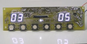
You mean something like this (attached pictures)?
I just completed the first module of the new integrated SD-playback system, the SD-transport.
The compact module measures only 45 x 160mm and includes display, keys, processors, opto-coupler for remote control, 3.3V regulator and display LC filter.
It has following connections;
J1, +5V power supply (approx. 0.6 Watts).
J2, 11.2896 clock input.
J3, SD-card holder.
J4, I2S output (not reclocked).
J5, remote control input.
After connecting it to the SD-player DAC & power supply, it worked first time without any corrections. Sound is even more transparent and detailed compared to the integrated SD-transport of the SD-player.
Next up are the 3-crystal super clock with integrated synchronous reclocker and the high resolution DC-coupled bridge power amp modules.
I plan to have a prototype of the integrated SD-playback system up and running in January. The device will be fully modular with many possible configurations. The device has both, local controls (volume control knob and push buttons), and a remote control function.
I am confident all modules will easily fit in the DI8M housing, high resolution tube output for TDA1541A might be one of the possible options.
yes, after designing some single-PCB projects, modular approach is most practical, especially for tuning.
You know I don't want to tamper with original audio data before the exact consequences of such manipulation in the digital domain are fully understood. I am referring to remains of studio clock jitter (spectrum) encapsulated in the sample values.
There is always room for improvement, but at some point one has to wrap it up and finalize a design. Thats what I am planning to do now.
This is what I do since 3 years by now. You can't beat that on performance and cost.
I fully agree with this, full integration of an audio set is the next logical step in optimizing sound quality. Interlinks cause much more sound quality degradation than expected, best is using soldered point-to-point wiring.
This basically requires integration of audio components in one box.
Of course what you loose is flexibility. Especially as a commercial
product you limit your adressable market. People probably won't buy all-in-one solutions in the audio world very often.
My primary objective is ultimate sound quality, not expanding a possible market.
I'd guess that the majority of people are looking for a transport with an I2S interface coming with a good jitter performance first of all.
You mean something like this (attached pictures)?
I just completed the first module of the new integrated SD-playback system, the SD-transport.
The compact module measures only 45 x 160mm and includes display, keys, processors, opto-coupler for remote control, 3.3V regulator and display LC filter.
It has following connections;
J1, +5V power supply (approx. 0.6 Watts).
J2, 11.2896 clock input.
J3, SD-card holder.
J4, I2S output (not reclocked).
J5, remote control input.
After connecting it to the SD-player DAC & power supply, it worked first time without any corrections. Sound is even more transparent and detailed compared to the integrated SD-transport of the SD-player.
Next up are the 3-crystal super clock with integrated synchronous reclocker and the high resolution DC-coupled bridge power amp modules.
I plan to have a prototype of the integrated SD-playback system up and running in January. The device will be fully modular with many possible configurations. The device has both, local controls (volume control knob and push buttons), and a remote control function.
I am confident all modules will easily fit in the DI8M housing, high resolution tube output for TDA1541A might be one of the possible options.
At least you continue following a modular approach. That's good to hear.
yes, after designing some single-PCB projects, modular approach is most practical, especially for tuning.
Perhps one day we'll even see 24bit, which would make data manipulation (e.g. volume control) on the PC without the need for dithering possible.
I was thinking about that. Shaping my data prior to storing them on the SD-card.
You know I don't want to tamper with original audio data before the exact consequences of such manipulation in the digital domain are fully understood. I am referring to remains of studio clock jitter (spectrum) encapsulated in the sample values.
I guess there won't be much space left for a "mkII" once you're finished
There is always room for improvement, but at some point one has to wrap it up and finalize a design. Thats what I am planning to do now.
Attachments

I think the most practical would be a spdif out and 44,1 kHz wordclock in.
Optical connections.
Optical connections.
Hi folks.
I had the pleasure to visit John yesterday again. I listened to his new protoype modules.
I do understand now why all the delay. His decision to switch to a modular design approach is for sure the best approach to keep the whole solution flexible ( for us).
Depending on how he plans to go to market with the stuff, he'll probably meet much more expectations by doing it this way.
All I can say about the modules - amazing engineering and performance.
Jitter discussions were yesterday as it seems.
His new master Ultra-precision-clock is feeding the processor and the DAC, all fed by a floating battery PS and his own 5V regulator.
No -- I guess you can't beat that approach. It won't allow for very much interference with other stuff.
I learned about a very interesting unique clock engineering and his wire-wound resistors and chokes. Very interesting. Winding the chokes by myself? Hmmh. It
requires real enthusiasm to go that road - that's for sure. 😀
I2S will be the interface of choice on the player module. Everything else is a compromise from his perspective and never achieve that performance. I buy that.
Very important: He plans to offer a mains and/or battery supply input. The listening session has shown again that the battery supply performs superior over mains supply. With a battery everything becomes crystal clean.
Do I sound like a sales man? Hmmh. Not intentionally. 😉
Where there is is light....
At least from my perspective -
1. volume control is one of the major questions. I'll never connect anything in between DAC and AMP again. What we discussed is a switchable passive I/V resistor divider on the output in rather large steps of 3-6db. This could be one of the best solutions I guess.
2. Currently supported I2S format , might prevent from hooking on all I2S DACs. ( This might change though)
3. Comfort - ease of use. I am used now to handle my collection easily via PC/iPhone remote. The SD-card approach would be a step back. On the other hand - If sound quality rules - who cares about comfort. John is aware of the subject. They will spent some thoughts about it.
4. I mentioned that before - lack of different bit-depths. This won't be an issue with 154x DACs of course. Different samplerates won't seem to be a major problem anymore due to the modular approach. Somehow the clocks would have to be made switchable.
John -- great to see the progress. Thanx for the sneak-preview yesterday. Looking forward to get one of your modules in my hands.
Cheers
Hi,
Glad to hear you're having fun. 🙂
On the power module part:
You are probably aware of the new Power JFETs used and discussed on Pass' forum, which are said to have triode-like transfer characteristics...expensive they are, but the inventor company directly sell at lower prices to audio companies for experimentation . 😉
SemiSouth Laboratories, Inc. | Power Semiconductors
Also, Ixis depletion mode MOSFET seem to be worthy of experimentation, as Mr Pass did.
Of course I will only copy others ideas...
Cheers,
M
Glad to hear you're having fun. 🙂
There is always room for improvement, but at some point one has to wrap it up and finalize a design. Thats what I am planning to do now.
On the power module part:
You are probably aware of the new Power JFETs used and discussed on Pass' forum, which are said to have triode-like transfer characteristics...expensive they are, but the inventor company directly sell at lower prices to audio companies for experimentation . 😉
SemiSouth Laboratories, Inc. | Power Semiconductors
Also, Ixis depletion mode MOSFET seem to be worthy of experimentation, as Mr Pass did.
Of course I will only copy others ideas...
Cheers,
M
4-crystal super clock/reclocker module
Hi maxlorenz,
I need complementary pairs (N-FET & P-FET), if I am correct, the power JFETs are only available as N-JFET. I am currently using 2 x 2SK1058 and 2 x 2SJ162 in the complementary H-bridge power buffer. Key factor however is power amp design.
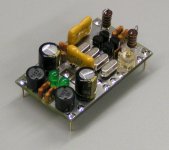
Meanwhile the second module of the Integrated SD-playback system has been completed and tested, its the new super clock / reclocker module. I added a photograph of this module. As you can see, a super clock doesn't need to be complicated.
The module contains 2 filtered LED shunt references (left). They provide both 4V power supply and 2V reference voltage. Decoupling was done using silvered mica caps, this was done based on both, measurements and listening tests. The complete module draws approx. 15mA @ 4V with one external clock load (SD-transport).
This super clock has 4 selected high-Q crystals (center). The crystals set oscillator frequency and perform oscillator output signal filtering. Fine-tuning is done with a Teflon trimmer.
Oscillation is maintained using a hybrid choke-loaded complementary JFET buffer. The gate resistor (100K bulk metal foil) connects to 2V reference voltage. The buffer produces both a 5Vpp square-wave and a 20Vpp sine wave output signal. These signal amplitudes are possible because of the hybrid chokes.
The 5Vpp square wave output signal is buffered by a matching hybrid choke-loaded complementary buffer and drives the SD-transport (1 clock load).
The 20Vpp low distortion filtered sine wave output drives a high-speed synchronous reclocker (located on the solder side) through a capacitive node. This capacitive node will have virtually no effect on crystal oscillator performance, it could be viewed as a wireless reclocker drive circuit. The reclocker is only a few millimeters away from the oscillator sine wave output, so it will perform way better than any external reclocker. The synchronous reclocker was preferred over a divider because a divider has more flip-flops and thus produces more jitter.
The synchronous reclocker has both, an external input and output. So one could reclock either BCK or WS.
The final design will be placed on HF PCB material (Teflon or comparable material). It also needs to be screened, I am thinking of a 2-layer screen consisting of copper and mu-metal.
In order to squeeze maximum performance out of this super clock, I used a 20th order LC power supply low-pass filter (10 x L, 10 x C) that also limits the current for the on-board shunt regs.
Hi maxlorenz,
On the power module part:
You are probably aware of the new Power JFETs used and discussed on Pass' forum, which are said to have triode-like transfer characteristics...expensive they are, but the inventor company directly sell at lower prices to audio companies for experimentation .
I need complementary pairs (N-FET & P-FET), if I am correct, the power JFETs are only available as N-JFET. I am currently using 2 x 2SK1058 and 2 x 2SJ162 in the complementary H-bridge power buffer. Key factor however is power amp design.
Meanwhile the second module of the Integrated SD-playback system has been completed and tested, its the new super clock / reclocker module. I added a photograph of this module. As you can see, a super clock doesn't need to be complicated.
The module contains 2 filtered LED shunt references (left). They provide both 4V power supply and 2V reference voltage. Decoupling was done using silvered mica caps, this was done based on both, measurements and listening tests. The complete module draws approx. 15mA @ 4V with one external clock load (SD-transport).
This super clock has 4 selected high-Q crystals (center). The crystals set oscillator frequency and perform oscillator output signal filtering. Fine-tuning is done with a Teflon trimmer.
Oscillation is maintained using a hybrid choke-loaded complementary JFET buffer. The gate resistor (100K bulk metal foil) connects to 2V reference voltage. The buffer produces both a 5Vpp square-wave and a 20Vpp sine wave output signal. These signal amplitudes are possible because of the hybrid chokes.
The 5Vpp square wave output signal is buffered by a matching hybrid choke-loaded complementary buffer and drives the SD-transport (1 clock load).
The 20Vpp low distortion filtered sine wave output drives a high-speed synchronous reclocker (located on the solder side) through a capacitive node. This capacitive node will have virtually no effect on crystal oscillator performance, it could be viewed as a wireless reclocker drive circuit. The reclocker is only a few millimeters away from the oscillator sine wave output, so it will perform way better than any external reclocker. The synchronous reclocker was preferred over a divider because a divider has more flip-flops and thus produces more jitter.
The synchronous reclocker has both, an external input and output. So one could reclock either BCK or WS.
The final design will be placed on HF PCB material (Teflon or comparable material). It also needs to be screened, I am thinking of a 2-layer screen consisting of copper and mu-metal.
In order to squeeze maximum performance out of this super clock, I used a 20th order LC power supply low-pass filter (10 x L, 10 x C) that also limits the current for the on-board shunt regs.
Attachments
Hi EC,
That new superclock looks great and I'm sure it "sounds" also great. Now we have to hear it by ourselves... 😉
I only mentioned that power J-FETs because of other power options...as I use fullrange drivers I am happy with a few watts given by single ended class A for example.
Best of lucks.
M
That new superclock looks great and I'm sure it "sounds" also great. Now we have to hear it by ourselves... 😉
I only mentioned that power J-FETs because of other power options...as I use fullrange drivers I am happy with a few watts given by single ended class A for example.
Best of lucks.
M
Are the 4 crystals in your clock module output in parallel? Do you have a schematic of your clock module?
Hi agent.5
The crystals are placed in series, yes I have a schematic of this clock module, I could publish it (commercial use not allowed).
I modified power supply decoupling by using 805 size 1uF NPO capacitors that are soldered directly across the synchronous reclocker power supply pins and across the crystal oscillator power supply. The silvered mica capacitors were removed.
I also built both SD-transport and clock / reclocker on HF PCB material for testing.
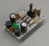
The attached pictures show the version built on HF PCB material.
First picture shows the component side, the 100K bulk metal foil gate resistor is located above the PTFE trimmer. It is very important to use low noise gate resistors of lowest possible value. The often used 10 M Ohm resistors produce a lot of noise that reduces oscillator performance. The 4 JFETs form two complementary pairs, one for the oscillator, the other for the clock buffer. I used complementary pairs instead of a single JFET because these offer much better PSRR and less load-induced jitter.
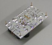
Second picture shows the solder side, the miniature (SOT232) flip-flop is located close to the 2 center pins (BCK/WS in, BCK/WS out). Two 805-size 1uF NPO caps are soldered on top for power supply decoupling. There is one bias resistor connected between FF clock input and the 2V reference voltage, and one in series with the BCK / WS input signal that connects to the FF data input. Clock signal path is kept very short, and this results in much better results compared to external reclockers connected through comparators, buffers and inches of wire.
Since this clock / reclocker module will be mounted on the DAC PCB, very short connection between both reclocker output and DAC timing input can be made.
The clock buffered output is used to drive the SD-transport.
Are the 4 crystals in your clock module output in parallel? Do you have a schematic of your clock module?
The crystals are placed in series, yes I have a schematic of this clock module, I could publish it (commercial use not allowed).
I modified power supply decoupling by using 805 size 1uF NPO capacitors that are soldered directly across the synchronous reclocker power supply pins and across the crystal oscillator power supply. The silvered mica capacitors were removed.
I also built both SD-transport and clock / reclocker on HF PCB material for testing.
The attached pictures show the version built on HF PCB material.
First picture shows the component side, the 100K bulk metal foil gate resistor is located above the PTFE trimmer. It is very important to use low noise gate resistors of lowest possible value. The often used 10 M Ohm resistors produce a lot of noise that reduces oscillator performance. The 4 JFETs form two complementary pairs, one for the oscillator, the other for the clock buffer. I used complementary pairs instead of a single JFET because these offer much better PSRR and less load-induced jitter.
Second picture shows the solder side, the miniature (SOT232) flip-flop is located close to the 2 center pins (BCK/WS in, BCK/WS out). Two 805-size 1uF NPO caps are soldered on top for power supply decoupling. There is one bias resistor connected between FF clock input and the 2V reference voltage, and one in series with the BCK / WS input signal that connects to the FF data input. Clock signal path is kept very short, and this results in much better results compared to external reclockers connected through comparators, buffers and inches of wire.
Since this clock / reclocker module will be mounted on the DAC PCB, very short connection between both reclocker output and DAC timing input can be made.
The clock buffered output is used to drive the SD-transport.
Attachments
- Status
- Not open for further replies.
- Home
- Source & Line
- Digital Source
- Lossless SD-card player