Hi jkeny,
These products were indeed developed within stated time period (also documented on both threads I started).
It doesn't take much time to develop and build something, most time is required by visualizing problems and possible solutions. I may think about specific problems for months, then come up with a solution and build a working prototype within a day like with the bridge power amplifiers or latest sonic resonators for example.
Other projects like the SD-player take more time to get both hardware and software functioning as planned. The SD-player was the most complicated project we (my brother and I) ever completed, it may look simple, but it sure isn't.
The designs completed over the last weeks aren't optimal, but what is. They were based on the theory that audio sets that offer higher resolution would be able to perform better. I was always forced to complete designs within a short time period, so that's nothing special for me.
Please read the post about resolution on my other thread. DAC chips are "selected" on properties like low THD, SN ratio and bit depth / sample rate. In my humble opinion these aren't the specs we should be looking for when striving for most realistic sound quality reproduction.
If we would select DAC chips on parameters like resolution (not bit resolution), things might look quite different, and the DAC chips I am using in my designs might just perform pretty well with resolution as important parameter.
DAC chip implementation has big impact on performance, its easy to construct 2 DACs using the same DAC chip while offering completely different performance levels.
The audio set needs to act as one fine-tuned system, like a well trained and experienced choir that sings, rather than a group of people without any musical skills attempt to sing a song. Changing one component in an audio set might have similar impact as placing somebody without musical skills in an orchestra, the false notes produced will spoil the sound of the entire performance.
That's the reason why I had to redesign my entire audio set, to create an audio set that acts as one well-tuned system .
I already explained the purpose of I2S attenuators, it's basically to reduce the amount of HF interference energy being coupled into the DAC chip substrate. The goal is achieving lower on-chip ground-bounce, and lower on-chip timing jitter. I2S interference is a major issue with all DAC chips.
The dynamic jitter attenuator works and it's an important part in the SD-player. It reduces the impact of BCK jitter on sample timing by dynamically changing the exact moment the DAC output latch triggers, in such way that it compensates for timing deviations. This reduces the effects of jitter produced by the master clock and the synchronous reclocker (d flip-flop).
Jitter measurements could be performed when the SD-player becomes available, you can measure jitter on the master clock, after the synchronous reclocker, or at the DAC output. You can use various power supplies like mains adapter lead-acid battery, NiMH , NiCD or Alkaline, they will all affect jitter spectrum. The connected test equipment will affect performance for sure (ground loops, probe capacity, and so on). Then you end up with a graph that basically still tells little about perceived sound quality.
Suppose jitter levels were exceptionally low, say -210dB, would that guarantee best sound? well, this depends on jitter spectrum too, the problem is, how to translate a plot of the jitter spectrum to perceived sound quality. When a measurement is made, test equipment needs to be connected to the test object, when measuring low level signals, this will affect measurements, in other words, it's likely that the tested object performs better (with test probe removed) than the measurement data would suggest. If the jitter measurement equipment uses a reference oscillator, it cannot perform accurate measurements below the intrinsic jitter of this reference clock.
The best test (that avoids inducing extra timing jitter) is using high quality CD recordings like from Stockfish recordings for example, and listening tests. I am convinced that a trained ear is more accurate than any known measuring device. It will not only reveal the presence of jitter, it will also immediately show the exact impact of the jitter spectrum on perceived sound quality. These listening tests are best conducted using an audio set capable of providing highest possible resolution.
Target is achieving a situation where experienced listeners can't tell the difference between live performance and the reproduction. It's not about spectacular or impressive sound, it's about utmost transparency.
High End audio is just my hobby, If I had to live from profit made with audio equipment I would have gone bankrupt by now. I also share development information (schematics) and write detailed explanations, not common practice with snake oil salesmen, besides I am a developer, not a salesman.
About the SD-player jitter, this is only one of many factors that determine SD-player perceived sound quality.
I wasn't talking about any delay (I'm not really in the market for this product) but just the development of new amp, speakers & SD player in such a short time seems superhuman
These products were indeed developed within stated time period (also documented on both threads I started).
It doesn't take much time to develop and build something, most time is required by visualizing problems and possible solutions. I may think about specific problems for months, then come up with a solution and build a working prototype within a day like with the bridge power amplifiers or latest sonic resonators for example.
Other projects like the SD-player take more time to get both hardware and software functioning as planned. The SD-player was the most complicated project we (my brother and I) ever completed, it may look simple, but it sure isn't.
EcDesigns is very specific to the TDAXXX range of DACs wher he has used Henk's idea (first muted on DIYA) to bias the signal around 1.2V AFAIR. His idea of jitter attenuation, he dropped (as it was too picky) but I see now it's back - to be honest, he's losing credibility with me - he redesigned a new amplifier & speakers in the weeks that he wasn't posting here - hard to believe that it's optimal
The designs completed over the last weeks aren't optimal, but what is. They were based on the theory that audio sets that offer higher resolution would be able to perform better. I was always forced to complete designs within a short time period, so that's nothing special for me.
Please read the post about resolution on my other thread. DAC chips are "selected" on properties like low THD, SN ratio and bit depth / sample rate. In my humble opinion these aren't the specs we should be looking for when striving for most realistic sound quality reproduction.
If we would select DAC chips on parameters like resolution (not bit resolution), things might look quite different, and the DAC chips I am using in my designs might just perform pretty well with resolution as important parameter.
DAC chip implementation has big impact on performance, its easy to construct 2 DACs using the same DAC chip while offering completely different performance levels.
The audio set needs to act as one fine-tuned system, like a well trained and experienced choir that sings, rather than a group of people without any musical skills attempt to sing a song. Changing one component in an audio set might have similar impact as placing somebody without musical skills in an orchestra, the false notes produced will spoil the sound of the entire performance.
That's the reason why I had to redesign my entire audio set, to create an audio set that acts as one well-tuned system .
I already explained the purpose of I2S attenuators, it's basically to reduce the amount of HF interference energy being coupled into the DAC chip substrate. The goal is achieving lower on-chip ground-bounce, and lower on-chip timing jitter. I2S interference is a major issue with all DAC chips.
The dynamic jitter attenuator works and it's an important part in the SD-player. It reduces the impact of BCK jitter on sample timing by dynamically changing the exact moment the DAC output latch triggers, in such way that it compensates for timing deviations. This reduces the effects of jitter produced by the master clock and the synchronous reclocker (d flip-flop).
Also, I keep asking him to get the unit tested for jitter (as this is what the whole point of the development is about) but so far no jitter measures!
Jitter measurements could be performed when the SD-player becomes available, you can measure jitter on the master clock, after the synchronous reclocker, or at the DAC output. You can use various power supplies like mains adapter lead-acid battery, NiMH , NiCD or Alkaline, they will all affect jitter spectrum. The connected test equipment will affect performance for sure (ground loops, probe capacity, and so on). Then you end up with a graph that basically still tells little about perceived sound quality.
Suppose jitter levels were exceptionally low, say -210dB, would that guarantee best sound? well, this depends on jitter spectrum too, the problem is, how to translate a plot of the jitter spectrum to perceived sound quality. When a measurement is made, test equipment needs to be connected to the test object, when measuring low level signals, this will affect measurements, in other words, it's likely that the tested object performs better (with test probe removed) than the measurement data would suggest. If the jitter measurement equipment uses a reference oscillator, it cannot perform accurate measurements below the intrinsic jitter of this reference clock.
The best test (that avoids inducing extra timing jitter) is using high quality CD recordings like from Stockfish recordings for example, and listening tests. I am convinced that a trained ear is more accurate than any known measuring device. It will not only reveal the presence of jitter, it will also immediately show the exact impact of the jitter spectrum on perceived sound quality. These listening tests are best conducted using an audio set capable of providing highest possible resolution.
Target is achieving a situation where experienced listeners can't tell the difference between live performance and the reproduction. It's not about spectacular or impressive sound, it's about utmost transparency.
I can accept his statement that he has achieved low jitter but less subjective evaluation criteria are needed, I feel. Maybe I've been overly sensitised by snake oil salesmen?
High End audio is just my hobby, If I had to live from profit made with audio equipment I would have gone bankrupt by now. I also share development information (schematics) and write detailed explanations, not common practice with snake oil salesmen, besides I am a developer, not a salesman.
About the SD-player jitter, this is only one of many factors that determine SD-player perceived sound quality.
Project update,
I spent a lot of time optimizing and redesigning my audio set in order to achieve sufficient resolution to further improve the SD-player.
Power amp performance was improved by adding miniature honeycomb chokes for improved performance of both input and driver stage.
I also had to redesign my sonic resonators, using a semi 2-way system. The passive crossover filter was optimized using hybrid capacitors, I used a V-cap TFTF as reference and managed to get much higher resolution using the hybrid caps. The idea is to minimize material resonances in each cap by reducing power dissipation in each cap, and to enable combining specific properties of capacitors.
After testing a lot of chokes, I used planar honeycomb chokes with high Q factor and low stray capacitance. Stray capacitance of chokes can cause unwanted trebles roll-off (unwanted stray capacitance in parallel with the tweeter) and short-circuit of the power amp at specific frequencies (stray low pass filter choke capacitance in series with low pass filter capacitor). The low-pass filter choke stray capacitance can cause power amp instability and unwanted oscillations.
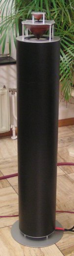
I added a photograph of the new passive crossover filter prototype. The planar honeycomb chokes were made using a removable frame and were fixated using construction glue. The wire is litz wire (multiple insulated strands). The next photograph shows the completed sonic resonator.
After improving the audio set I was able to further increase SD-player performance. The following modifications were made:
- I/V resistors were changed to non-inductive wire wound resistors using honeycomb choke construction in order to minimize stray capacitance. Wire length for each resistor equals 6.8 meters. This had tremendous impact on sound quality. I added a photograph of these non-inductive wire wound honeycomb resistors. They are wound on a CNC milled frame of PCB material with a plastic 5mm high spacer in the center.
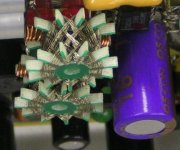
- Power supply filtering was improved using hybrid chokes consisting of multiple ferrite beads, a miniature 150uH honeycomb choke, and multiple 2.2mH chokes in series. The idea was achieving lowest possible stray capacitance, thus creating a true "open loop" power supply by maximizing series impedance. I added a photograph that shows both a honeycomb choke and a spiderweb choke for the master clock power supply. The spiderweb choke will be replaced with a honeycomb choke later.
The filters aren't only intended for mains powered operation, the effect on sound quality also applies for battery power supply. Battery power supply provides best clarity, transparency, and resolution.
With the complete audio set tuned, and the SD-player improvements, the sound quality has improved way beyond expectation. I never imagined that plain 16 bit recordings could hold such detail and transparency. Key factor turned out to be resolution.
In order to increase resolution I used following basics:
- Lowest possible jitter on all clock and data signals.
- DAC chip with simplest circuit, the fewer on-chip components, the better.
- Fewest (active) components in the signal path.
- best possible properties for each component.
- Avoiding coupling caps and transformers in the signal path when possible, full DC-coupling is ideal.
- Using FETs or tubes for amplification.
- No global feedback anywhere in the signal path.
- No current sources or current mirrors in amplifier stages.
- Super clean "open loop" power supplies.
Resolution doesn't show up in THD, S/N or settling time parameters. One can have low THD, good S/N ratio, and short settling time, and still end up with lousy resolution and resulting poor and artificial sound quality.
I spent a lot of time optimizing and redesigning my audio set in order to achieve sufficient resolution to further improve the SD-player.
Power amp performance was improved by adding miniature honeycomb chokes for improved performance of both input and driver stage.
I also had to redesign my sonic resonators, using a semi 2-way system. The passive crossover filter was optimized using hybrid capacitors, I used a V-cap TFTF as reference and managed to get much higher resolution using the hybrid caps. The idea is to minimize material resonances in each cap by reducing power dissipation in each cap, and to enable combining specific properties of capacitors.
After testing a lot of chokes, I used planar honeycomb chokes with high Q factor and low stray capacitance. Stray capacitance of chokes can cause unwanted trebles roll-off (unwanted stray capacitance in parallel with the tweeter) and short-circuit of the power amp at specific frequencies (stray low pass filter choke capacitance in series with low pass filter capacitor). The low-pass filter choke stray capacitance can cause power amp instability and unwanted oscillations.
I added a photograph of the new passive crossover filter prototype. The planar honeycomb chokes were made using a removable frame and were fixated using construction glue. The wire is litz wire (multiple insulated strands). The next photograph shows the completed sonic resonator.
After improving the audio set I was able to further increase SD-player performance. The following modifications were made:
- I/V resistors were changed to non-inductive wire wound resistors using honeycomb choke construction in order to minimize stray capacitance. Wire length for each resistor equals 6.8 meters. This had tremendous impact on sound quality. I added a photograph of these non-inductive wire wound honeycomb resistors. They are wound on a CNC milled frame of PCB material with a plastic 5mm high spacer in the center.
- Power supply filtering was improved using hybrid chokes consisting of multiple ferrite beads, a miniature 150uH honeycomb choke, and multiple 2.2mH chokes in series. The idea was achieving lowest possible stray capacitance, thus creating a true "open loop" power supply by maximizing series impedance. I added a photograph that shows both a honeycomb choke and a spiderweb choke for the master clock power supply. The spiderweb choke will be replaced with a honeycomb choke later.
The filters aren't only intended for mains powered operation, the effect on sound quality also applies for battery power supply. Battery power supply provides best clarity, transparency, and resolution.
With the complete audio set tuned, and the SD-player improvements, the sound quality has improved way beyond expectation. I never imagined that plain 16 bit recordings could hold such detail and transparency. Key factor turned out to be resolution.
In order to increase resolution I used following basics:
- Lowest possible jitter on all clock and data signals.
- DAC chip with simplest circuit, the fewer on-chip components, the better.
- Fewest (active) components in the signal path.
- best possible properties for each component.
- Avoiding coupling caps and transformers in the signal path when possible, full DC-coupling is ideal.
- Using FETs or tubes for amplification.
- No global feedback anywhere in the signal path.
- No current sources or current mirrors in amplifier stages.
- Super clean "open loop" power supplies.
Resolution doesn't show up in THD, S/N or settling time parameters. One can have low THD, good S/N ratio, and short settling time, and still end up with lousy resolution and resulting poor and artificial sound quality.
Attachments

Oh, a new secret weapon: honeycombs. 😉
Bees knows that since primitive times! 😀
Looks very unique.
Bees knows that since primitive times! 😀
Looks very unique.
Bees knows that since primitive times! 😀
That's why I run by"bees" on the battery power rails. 😀
looks impressive ecd, but I cant help to wonder if those big discs of copper would pick up more EMF or radiate some?
Also, I'm going to make a pair of omnis my self. Settled for the 90 degree disperser as there is no difference between that and a parabolic and it's much easier to make.
Do you know if the surface of the deflector impacts the sound or dispersion in any way?
Also, I'm going to make a pair of omnis my self. Settled for the 90 degree disperser as there is no difference between that and a parabolic and it's much easier to make.
Do you know if the surface of the deflector impacts the sound or dispersion in any way?
Soundcheck,
You use Bybees to knock down battery noise, I think. Can you tell me something about this as I'm experimenting with batteries myself & I'm experiencing noise. I think this noise is coming from grounding issues & DC hash coming through from PC via USB DAC cable, however, I'm interested in optimising (is it ever optimised, as John has said?) my set-up. What sort of battery noise did you experience & how did much improvement did the bybess bring?
John, you use large chokes to do the same - same questions to you!
Last edited:
Soundcheck,
You use Bybees to knock down battery noise, I think. Can you tell me something about this as I'm experimenting with batteries myself & I'm experiencing noise. I think this noise is coming from grounding issues & DC hash coming through from PC via USB DAC cable, however, I'm interested in optimising (is it ever optimised, as John has said?) my set-up. What sort of battery noise did you experience & how did much improvement did the bybess bring?
John, you use large chokes to do the same - same questions to you!
As you know my PC is galvanically isolated (optical-USB). My DAC and Amp are fed
by batteries. I do not have any groundloops over PS in the system.
The Bybees do what's written about them. If it is really worth all the money ?? Don't ask me. For sure my creativity was not sufficient to give "HoneyComb Chokes" a try. 😉
I just wanted to squeeze the last bit out of it, without jeopardizing the slew rates in the
system very much.
From what you can read the Bybees were build to get the PS battery noise down on submarines.
From what you can read the Bybees were build to get the PS battery noise down on submarines.
Is that what the "military use" is about? I would have said Naval use 🙂
They are expensive - I wonder how John finds the chokes he used & does his new honeycomb chokes work even better? I just happen to have some nice litz wire which I could test it out with
Is that what the "military use" is about? I would have said Naval use 🙂
I see the pattern! Submarines, uncharted waters ,(...)
Bybees...
What do you see at the center of the pic?
http://picasaweb.google.com/lh/photo/PZfaGSeS0YuWlKVUDImcsg?feat=directlink
But of course I did not comment about it...here... 🙂
What do you see at the center of the pic?
http://picasaweb.google.com/lh/photo/PZfaGSeS0YuWlKVUDImcsg?feat=directlink
But of course I did not comment about it...here... 🙂
What do you see at the center of the pic?
http://picasaweb.google.com/lh/photo/PZfaGSeS0YuWlKVUDImcsg?feat=directlink
But of course I did not comment about it...here... 🙂
http://www.enjoythemusic.com/superioraudio/equipment/0803/dodsonda218.htm
yeah, how about checking out Bybee's DAC according to 6moons "mag".
wow, upsampling...algorithm with -117 SNR... "directly interfering" with signal integrity ... thats funny, as an src4192 does -144

http://www.enjoythemusic.com/superioraudio/equipment/0803/dodsonda218.htm
yeah, how about checking out Bybee's DAC according to 6moons "mag".
wow, upsampling...algorithm with -117 SNR... "directly interfering" with signal integrity ... thats funny, as an src4192 does -144
Not that it matters, I've said it before and I'll say it again "quantum noise" is ** plain and simple.
Hi soundcheck,
Check the datasheets for opto-coupler capacitance between transmitter(s) and receiver(s). I am afraid there is still a HF coupling between both computer and DAC enabling HF noise (plenty of this available in a computer) to reach and pollute the DAC electronics.
I know many people would disagree with me, but I personally think that high performance computer-based digital audio playback with currently available consumer computer hardware is not possible.
here is a description of the Bybees:
quote "Quantum Purifier comprises damping and shielding materials surrounding a special ceramic, which in turn surrounds a resistor. The ceramic is made of numerous rare-earth metal oxides; the formula is still classified by the U.S. military".
I wouldn't be surprised if it's a modified ferrite bead.
If I am correct, the original Bybees are no longer manufactured.
http://www.enjoythemusic.com/Magazine/equipment/0702/bybee.htm
Honeycomb chokes are less "mysterious". It's a winding technique that increases the distance between wires that run in parallel, and minimizes the surface area where the wires touch. This results in much lower stray capacitance between the choke terminals compared to conventional chokes where all wires touch over a much larger surface area.
In short, it's a choke that offers low stray capacitance.
Here is an explanation where and why I used them in my audio set:
1) Wire wound passive I/V resistors.
I use wire wound I/V resistors to achieve low noise levels. But with common non-inductive winding techniques, stray capacitance is rather high as the wires touch over a large surface area. I used the honey comb winding method in combination with non-inductive winding (mobius loop) by running two wires side by side with one peg offset. The result is a very low noise, non-inductive resistor with low stray capacitance. I use a different approach to brickwall filtering by maintaining relatively large bandwidth signal throughout the audio set right up to the speaker chassis.
2) Additional filtering of highly critical power supplies in the SD-player (masterclock, reclocker, and DAC chip). The honeycomb chokes with low stray capacitance do a better job of rejecting HF interference (noise) because of the higher impedance at these frequencies.
3) Increasing impedance for blocking HF (noise) in the bridge power amplifier input and driver stages.
4) Reducing stray capacitance of chokes in the passive crossover filters. Just look at a speaker crossover filter and imagine there is a capacitor (1 ... 10nF for example) in parallel with each choke. The following things might happen now:
- Power amplifier output is short-circuit at specific frequency range. High-pass choke stray capacitance in series with high-pass capacitor, and low pass choke stray capacitance in series with low pass capacitor.
- The tweeter is short-circuit at specific frequency range instead of receiving full power (high-pass).
This could very well lead to power amplifier instabilities (oscillations) and increased distortion at higher power levels.
Honeycomb chokes can be home-made with some effort, so they can be constructed at minimum cost, just a frame, some (stranded) lacquered copper wire, and some patience 🙂
Construction of a honeycomb choke requires a frame with an odd number of pegs (I used 11 pegs). The frame must be rigid, and the pegs must not be allowed to bend as a result of wire tension.
So for larger chokes, steel pins need to be used for the pegs in order to minimize bending. Since these steel pins cannot stay in the completed choke, they must be removed after fixating the choke. So the frame must be constructed in such way that it can be removed afterwards. I used steel pins covered with teflon tube for easy removal after fixating the choke with glue or lacquer.
The smaller chokes can have frames made of cheap PCB material (glass fiber enforced epoxy), and a plastic 5mm spacer. These can stay in the choke after completion.
Here is some information about construction of honeycomb, spider web and star chokes, use google translate:
http://www.jogis-roehrenbude.de/Spulenwickeln.htm
http://www.jogis-roehrenbude.de/Leserbriefe/Neumann.htm
http://www.jogis-roehrenbude.de/Leserbriefe/Schlemm-Wickelmaschine/Korbspulen.htm
The winding pattern can be further optimized by preventing exact alignment of subsequent windings. This however requires either a computer-controlled winding machine, or a lot of patience.
My prototype chokes and I/V resistors were wound by skipping 5 pegs and looping the wire around one peg instead of two.
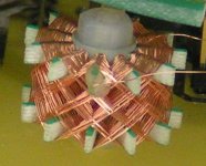
The choke diameter equals 2cm, and it's 9mm high. The PCB material is 2mm epoxy, and the pegs are 0.5mm wide and 2mm high. I didn't have a machine to wind these yet, this results in approx. 2 hours of hand-winding for each choke. I used 0.1mm thick lacquered copper wire, DC resistance of the completed choke is around 20 Ohms.
The I/V resistors (680 Ohms) were made using resistance wire (100 Ohms / meter) and a non-inductive honeycomb winding pattern. This is done by running two wires in parallel, with one peg spacing, creating a mobius loop.
I added a close-up of a miniature honeycomb choke for reference.
As you know my PC is galvanically isolated (optical-USB). My DAC and Amp are fed
by batteries. I do not have any groundloops over PS in the system.
Check the datasheets for opto-coupler capacitance between transmitter(s) and receiver(s). I am afraid there is still a HF coupling between both computer and DAC enabling HF noise (plenty of this available in a computer) to reach and pollute the DAC electronics.
I know many people would disagree with me, but I personally think that high performance computer-based digital audio playback with currently available consumer computer hardware is not possible.
here is a description of the Bybees:
quote "Quantum Purifier comprises damping and shielding materials surrounding a special ceramic, which in turn surrounds a resistor. The ceramic is made of numerous rare-earth metal oxides; the formula is still classified by the U.S. military".
I wouldn't be surprised if it's a modified ferrite bead.
If I am correct, the original Bybees are no longer manufactured.
http://www.enjoythemusic.com/Magazine/equipment/0702/bybee.htm
Honeycomb chokes are less "mysterious". It's a winding technique that increases the distance between wires that run in parallel, and minimizes the surface area where the wires touch. This results in much lower stray capacitance between the choke terminals compared to conventional chokes where all wires touch over a much larger surface area.
In short, it's a choke that offers low stray capacitance.
Here is an explanation where and why I used them in my audio set:
1) Wire wound passive I/V resistors.
I use wire wound I/V resistors to achieve low noise levels. But with common non-inductive winding techniques, stray capacitance is rather high as the wires touch over a large surface area. I used the honey comb winding method in combination with non-inductive winding (mobius loop) by running two wires side by side with one peg offset. The result is a very low noise, non-inductive resistor with low stray capacitance. I use a different approach to brickwall filtering by maintaining relatively large bandwidth signal throughout the audio set right up to the speaker chassis.
2) Additional filtering of highly critical power supplies in the SD-player (masterclock, reclocker, and DAC chip). The honeycomb chokes with low stray capacitance do a better job of rejecting HF interference (noise) because of the higher impedance at these frequencies.
3) Increasing impedance for blocking HF (noise) in the bridge power amplifier input and driver stages.
4) Reducing stray capacitance of chokes in the passive crossover filters. Just look at a speaker crossover filter and imagine there is a capacitor (1 ... 10nF for example) in parallel with each choke. The following things might happen now:
- Power amplifier output is short-circuit at specific frequency range. High-pass choke stray capacitance in series with high-pass capacitor, and low pass choke stray capacitance in series with low pass capacitor.
- The tweeter is short-circuit at specific frequency range instead of receiving full power (high-pass).
This could very well lead to power amplifier instabilities (oscillations) and increased distortion at higher power levels.
Honeycomb chokes can be home-made with some effort, so they can be constructed at minimum cost, just a frame, some (stranded) lacquered copper wire, and some patience 🙂
Construction of a honeycomb choke requires a frame with an odd number of pegs (I used 11 pegs). The frame must be rigid, and the pegs must not be allowed to bend as a result of wire tension.
So for larger chokes, steel pins need to be used for the pegs in order to minimize bending. Since these steel pins cannot stay in the completed choke, they must be removed after fixating the choke. So the frame must be constructed in such way that it can be removed afterwards. I used steel pins covered with teflon tube for easy removal after fixating the choke with glue or lacquer.
The smaller chokes can have frames made of cheap PCB material (glass fiber enforced epoxy), and a plastic 5mm spacer. These can stay in the choke after completion.
Here is some information about construction of honeycomb, spider web and star chokes, use google translate:
http://www.jogis-roehrenbude.de/Spulenwickeln.htm
http://www.jogis-roehrenbude.de/Leserbriefe/Neumann.htm
http://www.jogis-roehrenbude.de/Leserbriefe/Schlemm-Wickelmaschine/Korbspulen.htm
The winding pattern can be further optimized by preventing exact alignment of subsequent windings. This however requires either a computer-controlled winding machine, or a lot of patience.
My prototype chokes and I/V resistors were wound by skipping 5 pegs and looping the wire around one peg instead of two.
The choke diameter equals 2cm, and it's 9mm high. The PCB material is 2mm epoxy, and the pegs are 0.5mm wide and 2mm high. I didn't have a machine to wind these yet, this results in approx. 2 hours of hand-winding for each choke. I used 0.1mm thick lacquered copper wire, DC resistance of the completed choke is around 20 Ohms.
The I/V resistors (680 Ohms) were made using resistance wire (100 Ohms / meter) and a non-inductive honeycomb winding pattern. This is done by running two wires in parallel, with one peg spacing, creating a mobius loop.
I added a close-up of a miniature honeycomb choke for reference.
Attachments
Hi John.
You might have some good points here.
Though you should consider that the discussed items are at least available. I try to approach things from an "effort-benefit" perspective. Otherwise I'd be getting nowhere.
I probably will never build honeycombs, resistors or wooden caps by myself. That's just
too much.
Looking forward to your player. Any new go-to-market dates fixed?
Hopefully honeycombs won't lift the player in a price league far above earlier made announcements. 😉
Thanks -EC- for showing your coil/resistor. That one maybe easier for me to wind compared to your previous Moebius loop. Two hours is what a football match broadcast lasts... 😀
(apart the fact that I still have a few Km of OCC copper wire)
On the contrary 🙂 that is DIY! And if John is right (again) about the sound, it would be even cheaper than low noise super especial resistors...
I, myself, am considering DIY speaker drivers also, now that I disassembled one of my big coaxials
Cheers,
M
(apart the fact that I still have a few Km of OCC copper wire)
I probably will never build honeycombs, resistors or wooden caps by myself. That's just too much.
On the contrary 🙂 that is DIY! And if John is right (again) about the sound, it would be even cheaper than low noise super especial resistors...
I, myself, am considering DIY speaker drivers also, now that I disassembled one of my big coaxials
Cheers,
M
Thanks -EC- for showing your coil/resistor. That one maybe easier for me to wind compared to your previous Moebius loop. Two hours is what a football match broadcast lasts... 😀
(apart the fact that I still have a few Km of OCC copper wire)
On the contrary 🙂 that is DIY! And if John is right (again) about the sound, it would be even cheaper than low noise super especial resistors...
I, myself, am considering DIY speaker drivers also, now that I disassembled one of my big coaxials
Cheers,
M
I agree!
That resitors would be cheaper, but takes longer time to produce.
I hope that not be now longer time to wait SD card player.
Maxlorentz where did you get OCC wire?
regards,
Bostjan
Hi Bostjan 🙂
I have used OCC copper from various sources, even some bought here at the market place. When my stock was gone I decided to buy from here:
http://www.diytrade.com/china/4/products/1822685/Single_Crystal_Copper_Wire.html
32AWG. I am braiding interconnects Litz type, manually, which are very transparent and detailed. They take long to make but it is relaxing to do it (occupational therapy 😀 ).
Partsconnexion.com has some high quality OCC coper but at higher prices.
Cheers,
M
SD-player progress
Hi soundcheck,
The honeycomb winding pattern for the SD-player I/V resistors provides best results by far when compared to other resistors. The high power (wirewound) offers very low noise levels, the mobius loop construction offers low inductance, and the honeycomb pattern low self capacitance. There is much more resolution, and sound is more transparent. I already changed the frame-shape so fewer windings are required, this further reduces self capacity. is it worth the effort? I would say, yes, no doubt about it.
My brother completed a software application that fetches play lists from iTunes (through XML database), and writes contained songs to SD-card, converting them to WAV format "on the fly". Writing speed equals approx. 1 CD / minute. This small application greatly simplifies writing play lists to SD-card, now the SD-card concept becomes much more easy to use. It also means that files can be stored using Apple Lossless compression, saving disk space.
Sound quality comes first, I won't sell a single SD-player until highest possible sound quality (especially high resolution) is achieved while keeping SD-player cost as low as possible.
The SD-player hardware is currently being redesigned to offer even better performance, especially greatly increased resolution.
There is the new 3 ... 5 crystal masterclock with complementary drive circuit and dual discrete clock buffers that are integrated in the oscillator design in such way that jitter remains extremely low. I plan to design a larger masterclock module with integrated synchronous reclocker and filtered LED shunt regulators.
I2S attenuators are redesigned too, I now only pull the TDA1543 I2S inputs low (check TDA1543 I2S input circuit design). Logic "0" now corresponds with approx. 1V, derived by 1 x Schottky diode (0.4V) in series with one silicon diode (0.6V). Series resistor was added to reduce I2S input peak current. So one attenuator consists of 1 resistor in series with 2 diodes. The reason why I chose this solution is reducing components and preventing DAC 5V2 power supply pollution through I2S attenuator circuits.
Main 5V2 power supply performance was improved by adding a filtered precision current source to achieve more stable reference voltage and lower noise levels. Vref for the I/V resistors was split-up in two circuits, improving channel separation. Both masterclock and reclocker supply voltages are now also derived from the 5V2 main power supply, using cascaded, filtered LED shunt regulators.
Output coupling cap properties had to be changed in order to handle the high resolution signal. I currently use 4 caps (1 x 18pF silvered mica, 1 x 330pF silvered mica, 1 x 100nF polypropylene precision, 1 x 3.3uF polyester, and multiple low value series chokes and resistors). This hybrid cap offers better clarity and resolution than the V-cap TFTF that was used as reference. This basically means that capacitor specs (and resulting performance) can be tuned using multiple, carefully selected capacitors, chokes and resistors. Each capacitors must cover a specific frequency range that offers best performance with that cap (similar to a speaker crossover) so they cannot be connected directly in parallel.
The SD-player now provides highly transparent sound with extreme micro detail. It proves that it doesn't require a DAC chip with superior specs to achieve very high perceived sound quality. Key factor seems to be resolution (not bit resolution), rather than low THD.
I already attempted to explain what I mean with resolution and why it's so important. Here is the simplest example I can think of:
Imagine a mechanical construction with 100 sprockets placed in a chain, used for positioning. Every sprocket has certain play (say 0.1mm average for each sprocket). This means that when rotating the first sprocket in the chain, the last will only start moving after the backlash of this mechanical construction (99 x 0.1mm = 9.9mm) has been overcome. This basically means that 9.9mm movement reversals of the first sprocket won't result in movement of the last sprocket in the chain. This means that the precision or resolution of this system is limited to approx. 9.9mm.
Similar, imagine an electronic signal path with 100 components in that signal path (quite realistic when using Modern DAC chip, multiple Op-amps, pre amp, power amp / active speakers). Similar to above example, every component introduces an "electronic play", however so small, resulting in reduced resolution at the output. This means that both, small source timing and amplitude variations won't show up at the output. The resolution drops, micro details become inaudible, sound becomes grainy and artificial, and transparency is lost.
How could we easily improve resolution of the mechanical construction in above example? simply by minimizing the amount of sprockets, let's asume we would only use 10, then resolution would increase to 9 x 0.1mm = 0.9mm!
Similar, resolution in audio systems can be increased by reducing the amount of (active) parts in the signal path. Thus, simpler circuits with fewer parts in the signal path are likely to offer improved resolution.
Backlash can be reduced to very low values by eliminating mechanical (or electronic) play. This is method is often used in CD transports, using split, spring-loaded sprockets. With electronic parts it's not that easy, and parts must be selected for lowest "electronic play".
This includes all active and passive parts in the signal path.
Active part resolution, tubes offer highest resolution, electrons thavel through vacuum and electron flow is controlled by a static field. FETs offer next best resolution, electrons flow through solid material, electron flow is controlled by a static field. Bipolar transistors are worst, electrons flow through solid material and electron flow is controlled by a base current also flowing through that same solid material, causing unwanted interaction or interference between both currents.
Best passive parts for achieving high resolution are parts that are almost "ideal" like an ideal capacitor, inductor or resistor. This means that parts need to be selected very carefully, and the amount of passive parts in the signal path should be minimized too.
Hi soundcheck,
Though you should consider that the discussed items are at least available. I try to approach things from an "effort-benefit" perspective. Otherwise I'd be getting nowhere.
I probably will never build honeycombs, resistors or wooden caps by myself. That's just
too much.
The honeycomb winding pattern for the SD-player I/V resistors provides best results by far when compared to other resistors. The high power (wirewound) offers very low noise levels, the mobius loop construction offers low inductance, and the honeycomb pattern low self capacitance. There is much more resolution, and sound is more transparent. I already changed the frame-shape so fewer windings are required, this further reduces self capacity. is it worth the effort? I would say, yes, no doubt about it.
My brother completed a software application that fetches play lists from iTunes (through XML database), and writes contained songs to SD-card, converting them to WAV format "on the fly". Writing speed equals approx. 1 CD / minute. This small application greatly simplifies writing play lists to SD-card, now the SD-card concept becomes much more easy to use. It also means that files can be stored using Apple Lossless compression, saving disk space.
Looking forward to your player. Any new go-to-market dates fixed?
Sound quality comes first, I won't sell a single SD-player until highest possible sound quality (especially high resolution) is achieved while keeping SD-player cost as low as possible.
The SD-player hardware is currently being redesigned to offer even better performance, especially greatly increased resolution.
There is the new 3 ... 5 crystal masterclock with complementary drive circuit and dual discrete clock buffers that are integrated in the oscillator design in such way that jitter remains extremely low. I plan to design a larger masterclock module with integrated synchronous reclocker and filtered LED shunt regulators.
I2S attenuators are redesigned too, I now only pull the TDA1543 I2S inputs low (check TDA1543 I2S input circuit design). Logic "0" now corresponds with approx. 1V, derived by 1 x Schottky diode (0.4V) in series with one silicon diode (0.6V). Series resistor was added to reduce I2S input peak current. So one attenuator consists of 1 resistor in series with 2 diodes. The reason why I chose this solution is reducing components and preventing DAC 5V2 power supply pollution through I2S attenuator circuits.
Main 5V2 power supply performance was improved by adding a filtered precision current source to achieve more stable reference voltage and lower noise levels. Vref for the I/V resistors was split-up in two circuits, improving channel separation. Both masterclock and reclocker supply voltages are now also derived from the 5V2 main power supply, using cascaded, filtered LED shunt regulators.
Output coupling cap properties had to be changed in order to handle the high resolution signal. I currently use 4 caps (1 x 18pF silvered mica, 1 x 330pF silvered mica, 1 x 100nF polypropylene precision, 1 x 3.3uF polyester, and multiple low value series chokes and resistors). This hybrid cap offers better clarity and resolution than the V-cap TFTF that was used as reference. This basically means that capacitor specs (and resulting performance) can be tuned using multiple, carefully selected capacitors, chokes and resistors. Each capacitors must cover a specific frequency range that offers best performance with that cap (similar to a speaker crossover) so they cannot be connected directly in parallel.
The SD-player now provides highly transparent sound with extreme micro detail. It proves that it doesn't require a DAC chip with superior specs to achieve very high perceived sound quality. Key factor seems to be resolution (not bit resolution), rather than low THD.
I already attempted to explain what I mean with resolution and why it's so important. Here is the simplest example I can think of:
Imagine a mechanical construction with 100 sprockets placed in a chain, used for positioning. Every sprocket has certain play (say 0.1mm average for each sprocket). This means that when rotating the first sprocket in the chain, the last will only start moving after the backlash of this mechanical construction (99 x 0.1mm = 9.9mm) has been overcome. This basically means that 9.9mm movement reversals of the first sprocket won't result in movement of the last sprocket in the chain. This means that the precision or resolution of this system is limited to approx. 9.9mm.
Similar, imagine an electronic signal path with 100 components in that signal path (quite realistic when using Modern DAC chip, multiple Op-amps, pre amp, power amp / active speakers). Similar to above example, every component introduces an "electronic play", however so small, resulting in reduced resolution at the output. This means that both, small source timing and amplitude variations won't show up at the output. The resolution drops, micro details become inaudible, sound becomes grainy and artificial, and transparency is lost.
How could we easily improve resolution of the mechanical construction in above example? simply by minimizing the amount of sprockets, let's asume we would only use 10, then resolution would increase to 9 x 0.1mm = 0.9mm!
Similar, resolution in audio systems can be increased by reducing the amount of (active) parts in the signal path. Thus, simpler circuits with fewer parts in the signal path are likely to offer improved resolution.
Backlash can be reduced to very low values by eliminating mechanical (or electronic) play. This is method is often used in CD transports, using split, spring-loaded sprockets. With electronic parts it's not that easy, and parts must be selected for lowest "electronic play".
This includes all active and passive parts in the signal path.
Active part resolution, tubes offer highest resolution, electrons thavel through vacuum and electron flow is controlled by a static field. FETs offer next best resolution, electrons flow through solid material, electron flow is controlled by a static field. Bipolar transistors are worst, electrons flow through solid material and electron flow is controlled by a base current also flowing through that same solid material, causing unwanted interaction or interference between both currents.
Best passive parts for achieving high resolution are parts that are almost "ideal" like an ideal capacitor, inductor or resistor. This means that parts need to be selected very carefully, and the amount of passive parts in the signal path should be minimized too.
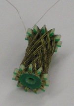
Hi maxlorenz,
Constructing a non-inductive (mobius loop) resistor with honeycomb winding pattern is rather difficult. The insulated constantine wire has a diameter of approx. 0.1mm and it tends to curl-up and get entangled very easily, rendering it useless. It requires a 2-chamber coil former to hold the thin wires during winding.
Since a mobius loop has to be made, one has to start at the center of the wire, meaning you fixate the center of the wire to the frame, and wind each wire on a separate part of the dual coil former. Two wires of 0.1mm must then be wound simultaneous on the frame with a spacing of 1 spoke.
You need to count the skipped spokes without making any error, especially until the first complete honeycomb pattern is formed. Then one can use the existing wire location for easier reference. With the final I/V resistor construction (19mm high and 12mm diameter holding 6.8 meters of wire) I skipped 7 spokes with 1 spoke offset.
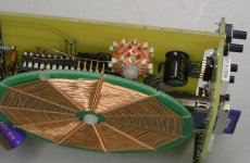
The I/V resistor is wound on a frame consisting of two small CNC-milled PCBs (2mm thick) and a 15mm high plastic spacer. I attached a photograph of this latest I/V resistor, it's 680 Ohms and there are fewer turns compared to the previous version. Because of tolerances in wire alignment caused by the increased resistor hight, self capacitance is further reduced.
The lead wires connect straight to the circuit in order to prevent adding extra solder joints. This I/V resistor offers very high resolution, way better than the bulk metal foils or copper wire I/V resistors that had too high self capacitance.
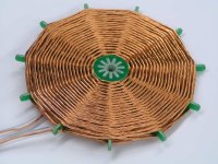
I also made a different construction for the SR60 crossover chokes. I use 11 CNC-milled spokes and two CNC-milled PCB disks that are then clamped together to form a non-removable frame. It requires quite some force (hammer) to lock each part firmly into position, tolerances are chosen such way that the frame is self supporting without requiring any glue.
The home made litz wire (I use 7 x 0.4mm and 12 x 0.4mm) is then wound on this PCB frame, this is quite easy to do. The lead-out wire is fixated by looping it through 2 holes drilled in one spoke. I attached a picture of the completed honeycomb choke (330uH).
Thanks -EC- for showing your coil/resistor. That one maybe easier for me to wind compared to your previous Moebius loop.
Constructing a non-inductive (mobius loop) resistor with honeycomb winding pattern is rather difficult. The insulated constantine wire has a diameter of approx. 0.1mm and it tends to curl-up and get entangled very easily, rendering it useless. It requires a 2-chamber coil former to hold the thin wires during winding.
Since a mobius loop has to be made, one has to start at the center of the wire, meaning you fixate the center of the wire to the frame, and wind each wire on a separate part of the dual coil former. Two wires of 0.1mm must then be wound simultaneous on the frame with a spacing of 1 spoke.
You need to count the skipped spokes without making any error, especially until the first complete honeycomb pattern is formed. Then one can use the existing wire location for easier reference. With the final I/V resistor construction (19mm high and 12mm diameter holding 6.8 meters of wire) I skipped 7 spokes with 1 spoke offset.
The I/V resistor is wound on a frame consisting of two small CNC-milled PCBs (2mm thick) and a 15mm high plastic spacer. I attached a photograph of this latest I/V resistor, it's 680 Ohms and there are fewer turns compared to the previous version. Because of tolerances in wire alignment caused by the increased resistor hight, self capacitance is further reduced.
The lead wires connect straight to the circuit in order to prevent adding extra solder joints. This I/V resistor offers very high resolution, way better than the bulk metal foils or copper wire I/V resistors that had too high self capacitance.
I also made a different construction for the SR60 crossover chokes. I use 11 CNC-milled spokes and two CNC-milled PCB disks that are then clamped together to form a non-removable frame. It requires quite some force (hammer) to lock each part firmly into position, tolerances are chosen such way that the frame is self supporting without requiring any glue.
The home made litz wire (I use 7 x 0.4mm and 12 x 0.4mm) is then wound on this PCB frame, this is quite easy to do. The lead-out wire is fixated by looping it through 2 holes drilled in one spoke. I attached a picture of the completed honeycomb choke (330uH).
Attachments
- Status
- Not open for further replies.
- Home
- Source & Line
- Digital Source
- Lossless SD-card player