House gnd is the green wire coming from the power cordJust to be clear Deaf, you install this where the house ground would normally go right to chassis?
See this link for a complete discussion of grounding and ground lift operation: https://www.cascadetubes.com/2020/01/13/grounding-philosophy/
I would suggest using a step down transformer from the pro audio industry such as 4:1 ratio or 10K:600Ω. That way, you can use common audio tubes like 12AU7 or 6SN7 without feedback to have gain of 3 or 4 or 5 (depends one how the tube plate is loaded). Some even have 8:1 ratio if you're stuck with high gain tubes like 12AX7 or 6SL7. And volume control can be low value from 600Ω to 2K. Also step-down transformers tend to have wider bandwidth than step-up ones. 10K or 15K is high enough input impedance to be driven by most sources. As a bonus you get balance input and can break ground loop. And to my ears, they sound better subjectively over straight to the pot. If your source can drive 600Ω, you can even flip around and have 1:4 step-up in front of a cathode follower. Use your creativity.
I really like this idea of using a 4:1 transformer at the input followed by a common cathode triode with gain of about 15x. In the end that will make a line stage with about 3X gain (or thereabouts).
It seems suitable quality 4:1 audio transformers are expensive. The Hammond one is open frame (no mu-metal case), so that's probably out of the running. The Jensen JT-10KB-D (10k:600) looks right, but it's $70 each, so that's $140 for a pair. This transformer does have a mu-metal can. The extra expense is all that would stop me from going this way. I would like to try this, though.
I'd use it on the input with a 6N6P or ECC99 common cathode stage, so the Zout would be roughly 2k ohms (maybe lower) and the total gain would be about +11dB (about 3.5X).
Some people like the sound you get with a good audio transformer in the signal chain. Remember that recordings are made with lots and lots of audio transformers in the signal chain. They can do nice things to the sound, although this is a matter of taste.
A good small signal audio transformer will also isolate the input of the preamp from ground loops, etc. (galvanic isolation) This can reduce noise in the system.
Also, some people absolutely hate the idea of having any negative feedback applied to their vacuum tube audio circuits, Just about all triodes have too much gain to be used as a line level preamp in a contemporary home playback setup, because most sources today already make 2V rms output all by themselves. There's no need for any gain, but applying 15X gain will increase noise (and possibly distortion) without doing anything actually good. Also, almost all triodes have too high an output impedance to drive contemporary amplifier inputs well (many of today's amplifiers have input Z of 5k or 10k ohms).
One solution would be to use a typical triode (like a 12AT7, 12AU7, 6SN7, 6N6P, 6DJ8) as an 'anode follower' with a negative feedback loop to lower its gain, output impedance and distortion. A cathode follower (or MOSFET source follower) could be added to buffer this circuit to help it drive the feedback loop better while also driving the external load of interconnect cable and amplifier input.
Another solution would be to use a triode with very low mu and low output impedance such as a 12B4A or a 6V6-triode. There are long threads on diyAudio about these kinds of things.
A different solution would be to use a line stage based on a cathode follower. This can help high impedance sources drive contemporary amplifiers with input impedance of 5k or 10k ohms, while not adding any gain (it would probably have about 0.9X gain, so there would be a little bit of insertion loss).
And finally, one could use a 4:1 input transformer to reduce the gain of the incoming signal (by 4X), so that 2V signal would now be 500mV. That would be followed by a triode common cathode amplifier stage, perhaps a 6N6P with gain of about 15X. The end result would be a line stage with gain of about 3X, high input impedance, galvanic isolation of its input, and decently low output impedance -- and all with no negative feedback loop applied (if that's important to you).
Another advantage is that you can wire the input transformer to make the output in phase with the input since the single gain stage phase is inverted due to odd number. You can add a switch to toggle between phases, if you like to play with that sort of things.The end result would be a line stage with gain of about 3X, high input impedance, galvanic isolation of its input, and decently low output impedance -- and all with no negative feedback loop applied (if that's important to you).
Here are two examples of using 1:1 bridging transformer from Stuart Yaniger's the Herectical preamp that has no gain and the Impasse preamp with gain.
I built a preamp once using mic transformers at the input, then a single 6J5 per channel and another transformer for output. I modified an old RCA mic preamp schematic to build it.Another advantage is that you can wire the input transformer to make the output in phase with the input since the single gain stage phase is inverted due to odd number. You can add a switch to toggle between phases, if you like to play with that sort of things.
Here are two examples of using 1:1 bridging transformer from Stuart Yaniger's the Herectical preamp that has no gain and the Impasse preamp with gain.

Here's an idea I had after directdriver's suggestions...
A pair of input transformers is going to cost a fair amount of money, and output transformers would be a complication (the thread does say 'simple'). So I figure the 4:1 input transformer is the important ingredient, and a cathode follower will drop the output impedance down to <500 ohms.

Does that count as simple? Or is that not simple enough?
A pair of input transformers is going to cost a fair amount of money, and output transformers would be a complication (the thread does say 'simple'). So I figure the 4:1 input transformer is the important ingredient, and a cathode follower will drop the output impedance down to <500 ohms.
Does that count as simple? Or is that not simple enough?
Last edited:
Another advantage of having input transformer to break ground is to make the circuit upside down, for fun, like below.Here's an idea I had after directdriver's suggestions...

There are mic transformers that are also suitable for line use such as UTC A-10 and HA-100X (500:50K) which were used in the different versions of the Teletronix LA2A opto compressor. With 1:10 step-up ratio going into a cathode follower AND a step-down output transformer (10K:600) you'd still have some gain left, less than 2.5 times!I built a preamp once using mic transformers at the input, then a single 6J5 per channel and another transformer for output. I modified an old RCA mic preamp schematic to build it.
Your 6J5 is likely wired as a gain stage so is your mic tranny wired backwards as step-down? Was it the RCA BA-2C? Any schematic?
It's been about 12 years since I built the thing. I pased it along to someone else a year later. I'm pretty sure the transformers I used at the input were UTC-10's though. For output I used Edcores, I do believe they were 10K or so:600's. I no longer have the RCA schematic. I do rember it sounding very clean and clear. The BA-2C sounds about right though. It had plenty of gain for my needs.There are mic transformers that are also suitable for line use such as UTC A-10 and HA-100X (500:50K) which were used in the different versions of the Teletronix LA2A opto compressor. With 1:10 step-up ratio going into a cathode follower AND a step-down output transformer (10K:600) you'd still have some gain left, less than 2.5 times!
Your 6J5 is likely wired as a gain stage so is your mic tranny wired backwards as step-down? Was it the RCA BA-2C? Any schematic?
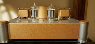
left out the link to the preamp I decided on.I've landed on this one as this is simple, I have 95% of the parts, it is for my desk so won't be using for critical listening. The chain is Qobuz on computer - simple preamp - 6LU8 compactron amp - Severely cobbled up RS Minimus 11s speakers.
View attachment 1086070View attachment 1086071View attachment 1086072
https://diyaudioprojects.com/Tubes/Universal-Tube-Preamplifier/
I thought about using one of those electrical boxes for my build. But when I saw how much they cost for being nothing more than a small plastic box, I made my own using an 1/8" aluminum plate and a bit of walnut wood for less money.left out the link to the preamp I decided on.
https://diyaudioprojects.com/Tubes/Universal-Tube-Preamplifier/
Is there any issues using a toroidal thransformer vs. the normal stand up type (don’t know what it’s called) transformer?
I've used both without issue. I built a 6l6 PP amp using a toroidal, along with a SE amp I built. My main preamp has one as well.
If your not used to using toroidal transformers, maybe ask first about how you want to mount it. It is possible to short out the windings if mounted wrong. The mounting bolt goes through the center, and you don't want the other end of the bolt grounded to the chassis, like if a cover is used. You want to have a bit of a gap if a cover attached to the mounting bolt. The cover I used on one I used has an 1/8" gap between the cover and chassis due to the mounting bolt screws into the cover. Both ends of the mounting bolt being grounded to the chassis is bad.
Attachments
- Home
- Amplifiers
- Tubes / Valves
- Looking for a simple tube preamp build