Late to the party, and perhaps not of interest, I designed it for use in my home office with a 5W per channel 6J7/6V6 amp, FM tuner, and Roon endpoint using RPI 4 and Topping DX-3 pro dac. It's pretty simple and will drive almost anything within reason. Its Achille's heal is it works best with a 6N6P having good section to section match.
https://www.diyaudio.com/community/...e-stage-w-parafeed-output-transformer.378535/
I have since added a small sub woofer and class D woofer amplifier with integrated crossover.
https://www.diyaudio.com/community/...e-stage-w-parafeed-output-transformer.378535/
I have since added a small sub woofer and class D woofer amplifier with integrated crossover.
This is what I've found also. None of my SS power amps or tube amps need an active preamp, but they all just sound better with one.About ten years ago, a bunch of SMAC friends came over and brought different amps with them. I had a tube preamp and a SS preamp to work with.
we had 8 amps to play with. Half were tube amps and half were SS amps.
we would put an amp on a preamp, turn the amp to full volume if it had a volume pot, then played tunes with volume set with a meter.
we did these with all the amps and preamps.
even thought the color of the music was different, in all cases the music was more dynamic than without a preamp.
that is what I am shooting for with building a preamp.
Use this as outputstage,
https://www.diyaudio.com/community/...c85-6922-6dj8-etc-mu-follower-or-srpp.388295/
And place a source selector switch and volume pot in front of it.
https://www.diyaudio.com/community/...c85-6922-6dj8-etc-mu-follower-or-srpp.388295/
And place a source selector switch and volume pot in front of it.
For my desktop I want simple. I just got back home after 10 days gone and last night I “think” I found enough parts for the simple pre.Use this as outputstage,
https://www.diyaudio.com/community/...c85-6922-6dj8-etc-mu-follower-or-srpp.388295/
And place a source selector switch and volume pot in front of it.
For me, it added a bit of hum. It's supposed to help if you wind up with a ground loop problem. With all the amps and sources I've tried this preamp with I haven't had any hum problems. After building and using this preamp, I should have just omitted the switch. Its a simple circuit. It would be easy enough to go back in and lift the ground if needed after building it.

This is how I grounded my 1200v ampThanks Lavane. I’ll build without to start with.
Use a diode bridge with enough amps to carry a short circuit
Attachments
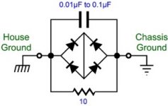
I do the same thing, for lower current applications 3 or 5A anti-parallel diodes work well in place of the bridge, but these applications are all primary fused at 1A or less. For safety the network needs to safely carry the full current. Note that safety GND is connected directly to the chassis and the ground lift network goes between the safety GND and the electronics PSU GND.
I would suggest using a step down transformer from the pro audio industry such as 4:1 ratio or 10K:600Ω. That way, you can use common audio tubes like 12AU7 or 6SN7 without feedback to have gain of 3 or 4 or 5 (depends one how the tube plate is loaded). Some even have 8:1 ratio if you're stuck with high gain tubes like 12AX7 or 6SL7. And volume control can be low value from 600Ω to 2K. Also step-down transformers tend to have wider bandwidth than step-up ones. 10K or 15K is high enough input impedance to be driven by most sources. As a bonus you get balance input and can break ground loop. And to my ears, they sound better subjectively over straight to the pot. If your source can drive 600Ω, you can even flip around and have 1:4 step-up in front of a cathode follower. Use your creativity.There seems to be a widespread aversion to any form of negative feedback imposed on a circuit (while forgetting the internal feedback mechanism in all triodes, or the degenerative feedback produced by leaving a cathode load resistor unbypassed), along with the fact that there are practically no suitable triodes with mu = 2 or 3.
Just to be clear Deaf, you install this where the house ground would normally go right to chassis?This is how I grounded my 1200v amp
Use a diode bridge with enough amps to carry a short circuit
Just had a thought. Normally the house group goes to the chassis then all the compound grounds go to chassis. If that is lifted the preamp will still work without house ground???For me, it added a bit of hum. It's supposed to help if you wind up with a ground loop problem. With all the amps and sources I've tried this preamp with I haven't had any hum problems. After building and using this preamp, I should have just omitted the switch. Its a simple circuit. It would be easy enough to go back in and lift the ground if needed after building it.
Same as car audio, airplane audio, space-station audio, pocket radio or iPod.the preamp will still work without house ground???
Safety ground / PE / house ground must be connected directly to chassis. Signal "ground" can be lifted from chassis, but, unless safety measures are taken, causes potentially dangerous conditions. For example, if lifted guitar-amp style, leakages make a voltage difference between chassis and input/output jacks, interconnect wiring, speakers and their wiring, etc. The double-diode bridge+resistor+cap keeps this leakage voltage to safe levels.
Its other function is to survive long enough to open the line fuse, which must be connected immediately at the AC wiring's line input. The absolute worst case would be a failure of that AC input line shorting to chassis before the fuse. In that worst case, the bridge+resistor+cap needs to survive long enough to open the house breaker. Makes ya worry less about all that work to file out a hole for an IEC power jack, rather than an easy round hole with grommet like the good old days.
All good fortune,
Chris
Good pointSame as car audio, airplane audio, space-station audio, pocket radio or iPod.
But I am having a hard time wrapping my head around what to do with all the grounds on a schematic if they don’t go to house ground. Is that what “lifted” means?Good point
I used to be confused about this too. I hope the following helps clarify:
https://www.valvewizard.co.uk/Grounding.html
https://www.valvewizard.co.uk/Grounding.html
Very nice Ron. I’m an extra on set of a TV show today and have a lot of time to read and digest the PDF.
The "house ground" is attached to the chassis near the power input. On all my amps I connect the negative side of the first filtering cap to a different point in the chassis and star ground everything to that point.But I am having a hard time wrapping my head around what to do with all the grounds on a schematic if they don’t go to house ground. Is that what “lifted” means?
The home I live in was built in '59. There are limited grounded outlets that have been added since. I didn't have any problems using this preamp without an earth ground.Just had a thought. Normally the house group goes to the chassis then all the compound grounds go to chassis. If that is lifted the preamp will still work without house ground???
- Home
- Amplifiers
- Tubes / Valves
- Looking for a simple tube preamp build