The 4M7 is driving into 470K in parallel with the preceding plate resister of 27K. As well as the plate of the triode. So actually less than 1/174.
At the other end the other 4M7 is driving into 470K in parallel with 33K & the very low R at the driver cathode. So almost no NFB at all.😱
The 150K driving back to the cathode of the other triode really is PFB. I & others often use it to get some gain.
Put your cct on the test bench try it for yourself. Do you have an AG & VM? Easty to do. No guessing required.🙂
Our ears don't lie. But our brain often does. Causing us to hear what we want to hear. Just as it does in politics!! My opinion, anyway.🙂
So, we need more resistance to the concertina and lower FB resistors and possibly a penthode for VAS. Off to inspect the box for 9-pinners. Would EF86 be a candidate? A=180, Vout 12V at 1,4%
Last edited:
The cct as shewn is not suitable for the kind of NFB you are proposing to use. The driver needs to be PP.🙂
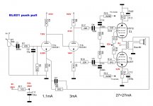
Ah, seul a LTP works because of the high load resistors... Meanwhile I changed to this: no more than 33V over the concertina. It's a sheer miracle but it's working already (@4mA, typo) 🙂 What could be expected when a CCS is put on top of the concertina? The former RC cathode connection functioned as a sort of loudness I found. The circuit was taken from the Dynaco ST35.
Attachments

Last edited:
I think you could make it work.
I don't want to go down the concertina Zout rabbit hole except to say that it is a cool circuit because when the plate and cathode loads are excactly equal, the plate and cathode circuit output have to mirror each other exactly. Despite the higher Zout at the plate, the circuit constraints don't allow it to deviate from being the mirror of the cathode circuit. So you end up getting some of the benefits of the low cathode Zout at the plate side. A notable exception is the PSRR, which is worse on the plate side.
So you would want to analyze this from the cathode side's point of view, which is low Zout, add series resistance to define a higher Zout at the cathode (like Rin of an inverting op-amp circuit). Then choose a feedback resistor that give the gain you are looking for. If you make everything exactly equal that loads the plate and cathode of the concertina (your schematic has some features that may impact this!), outputs will be the same.
Then you have to go over everything and make sure that you have enough voltage and current headroom to drive everything properly to the desired limits.
I have no doubt that this would give less distortion than UL because you are applying the error correction to the electrode that gave rise to the error in the first place, not some other electrode with other characteristics.
Not sure I know the whole circuit, but what difference does it make where the error correction is applied, as long it's all within the same overall loop?
Jan
Not sure I know the whole circuit, but what difference does it make where the error correction is applied, as long it's all within the same overall loop?
Jan
So in a multigrid tube, the different grids, when used as inputs, have different characteristics. So if you take an error signal derived from a control grid nonlinearity and apply the correction to another grid with different characteristics, you typically end up with an improvement but one that is not as good as if you applied that error correction to the control grid driving circuitry (the one that gave rise to the nonlinearity in the first place). Does that make sense?
Both ccts are very ordinary aside from one of them using the dissimilar 7247 twin triode. Half each of AX7 & AU7, they never really caught on. I used one in an amp more than 50 yrs ago. It performed OK but nothing exceptional at all.🙂Today rather rare & expect to pay a premium.
Design is a lot more than tube rolling.
Design is a lot more than tube rolling.
The voltage on the AT is too low for comfort.
This is more like it.
And don't forget to protect the AT grid from the high Vgk at start-up (diode or Ne bulb) .
Mona
This is more like it.
And don't forget to protect the AT grid from the high Vgk at start-up (diode or Ne bulb) .
Mona
Attachments
Last edited:
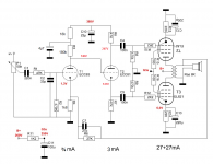
8 ohms. Works great btw, PG feedback. Authorotive, deep bass (on that hard to drive 2-way reflex, remember?). Highs could be better though, it tops off round 13KHz (by ears 😀) Serial resistance might be chosen a little high...
Had to experiment a little (Ketje was close, now it's spot on) with the T1 anode res as it sets the T2 stage. With tube life the operating point shifts so a current source might be called for.
The concertina is unity gain with equal output resistances (RL x ra) / (RL(u+2) + ra) = circa 273R per leg.
Oh, typo: T1=12ax7 T2=12at7
Attachments
Last edited:
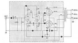
Circuit Modifications to EL821 Circuit, Comments
With the small local NFB modification you have made you have succeeded in converting an otherwise more than passable amplifier into a generator of some even order distortion (2nd, 4th, 6th,...). The OPT in your photo looks like quality, it will remove some of the problem you have inflicted upon the circuit.
The full loop NFB will reduce the problem even further, as it intended to do.
Experienced designers can see the problem without doing the math at all. Altho the output stage is balanced the driver is not. If the driver were replaced by a PP stage the problem as noted would disappear. But another problem shews up, triode D% increases as their load increases. Direct NFB to the previous plate increases loading, it is negative. Better to go to the previous stage cathode.
Designing an audio amplifier from the ground up is not a trivial exercise. And even more difficult without the proper tools, scope, Audio generator & so on. Your observation of the sound quality is subjective, others may not agree.
Deep bass could be nothing more than speaker resonance. An objective observation is the result of careful measurement, something that can be repeated anywhere & agreed open by others.
But if you are happy with the sound that is all that matters. Just as lots of distortion is what a rock guitarist looks for & needs. AND BTW, I like the Rolling Stones & Bach! And Pink Floyd.😀
Experienced designers can see the problem without doing the math at all. Altho the output stage is balanced the driver is not.
It seems to me that Kirchhoff might disagree. You seem hung up on the difference of calculated Zout at plate and cathode. I agree that if the load at the anode of the concertina were in some way unequal to the load at the cathode, there would be issues. But if you keep them exactly equal, the circuit constraints result in some cool behavior; mirrored outputs, which is what we want here.
Please set me straight here if I am wrong. I love to learn, but any type of imbalance here seems like it would break Kirchhoff's laws, which would shock me to say the least.
Edit: This is a debate that pops up here every few years and I've yet to see anyone prove with measurement or even sim that a concertina with balanced loads is somehow imbalanced due to the difference of Zout at plate and cathode.
The PSRR is another story, however, and worthy of some attention.
Last edited:
Mathematical proof of balance with equal loading on pages 460-462 of MJ Valve Amplifiers, 4th edition.
With the anode-grid feedback the concertina isn't dynamical loaded equal.The load depends on the voltage gain of the output tubes and those change in opposite direction.
Another possible problem, i think you have more hum now.
Mona
Another possible problem, i think you have more hum now.
Mona
The driver is balanced for output volts to the following stage so long as the impedance into which it drives is the same (grid resisters). Under ordinary conditions that holds true, altho at higher frequencies it falls apart. But at a frequency that does not cause a problem for audio.
In this case we see similar local short path NFB, but that is driving back into dissimilar impedances. The cathode output impednce is much lower than the plate output impedance for a split load phase invertor.
The result is the top output tube in the schema will get more NFB than the bottom tube.
So the top generator driving into the OPT has lower Z than the bottom tube.
And the OPT reacts to the unbalance & tries to fix it.
All fixed with a symmetrical driver. And the sun shines.
A Wave Anaalzer or FFT would quickly shew that. I've been using equipment from Pico Technology for about 20 yrs. In 1965 when I went into sales the same capability would have covered a couple of workbenches. And much hand recording of results. And cameras on scopes. Very big difference today.
Experimenters should spend part of their Gelt on good TE. Leave the boutique resisters & capacitors for later. Spend more time doing real tests, less time toob rolling. My opinion. anyway.🙂
Affordable test equipment is widely available today, much more so than when I still had hair. I built quite a bit of my own. Than at about 1955 I was lucky enough to go to work for a very well equipped R&D lab. They were doing a lot of work on early digital computers. A great place to be, many there were building Williamsons & so on.🙂
Last edited:
Out of curiousity, let's see what happens with shunt plate Fdbks to a Concertina triode splitter.
Let's say the input to the Concertina moves positive. This pulls the cathode driven output tube grid positive, which makes it's plate move negative. The negative delta back thru the Fdbk resistor to the Concertina cathode has little effect on the Concertina cathode V, but increases the current thru the Concertina to its plate. That pulls the Concertina plate negative, turning off the top output tube. Thus helping the bottom tube turn on. So net result there is positive Fdbk.
Now the top output tube would be turned off by the positive going input to the Concertina, and its plate would move positive. That positive delta back thru the top Fdbk resistor to the Concertina plate would pull the Concertina plate positive, producing Neg. Fdbk to the top output tube, as hoped. Not much passes back thru the Concertina in reverse if it is high mu.
So it would seem that these shunt Fdbks don't do anything for the bottom output tube,
and cancel out for the top output tube.
Result, NO Fdbk anywhere. A -Do Nothing- circuit, except it causes the Concertina gm to work harder, making a bit more distortion in the Concertina.
Last edited:
- Home
- Amplifiers
- Tubes / Valves
- Local feedback between grid-cathode