With the anode-grid feedback the concertina isn't dynamical loaded equal.The load depends on the voltage gain of the output tubes and those change in opposite direction.
Another possible problem, i think you have more hum now.
Mona
Ah yes, so we are talking about secondary effects of the imperfect virtual earth at the output tube grid. I didn't think they would be very significant.
What is the magnitude of the problem? Any reason to believe it would be worse in magnitude than the standard shortcomings of push-pull tube amps? Is this going to generate even-harmonics at anywhere near the magnitude of of standard odd-harmonics in a push-pull output stage?
I have nothing to measure. All of my designs use symmetrical drivers for other reasons.

Morgan Jones Analyzes the Concertina
Here is the condition I noted when applying the kind of local NFB used in the amplifier in the thread. All well explained by Morgan Jones.
An excellent reference book for Newbies & the Not So New.🙂
Just a few Guilders, Deutsch Marks, UK Pounds or Euros!
PS-I'm 1/16 Pennsylvania Deutsch. More later.
Here is the condition I noted when applying the kind of local NFB used in the amplifier in the thread. All well explained by Morgan Jones.
An excellent reference book for Newbies & the Not So New.🙂
Just a few Guilders, Deutsch Marks, UK Pounds or Euros!
PS-I'm 1/16 Pennsylvania Deutsch. More later.
Attachments

Out of curiousity, let's see what happens with shunt plate Fdbks to a Concertina triode splitter.
Which circuit are you talking about here? All of them or the ones before #113?
Here is the condition I noted when applying the kind of local NFB used in the amplifier in the thread. All well explained by Morgan Jones.
An excellent reference book for Newbies & the Not So New.🙂
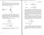
Right, my 4th edition concludes the analysis of the equally-loaded concertina stating, "Because Zk = Za, the frequency response at each output is forced to be the same, so the output resistances must also be equal, and rout(k) = rout(a)."
Of course, the caveat there is equal loading. Looking at the circuit in post #113, the output tube anodes have to mirror each other due to the coupling of windings in the transformer, so the voltages on the plate ends of the feedback resistors will always mirror one another, so will always present a load that is balanced at any instant in time to the cathodyne (through the caps and R17 and R18). The series resistors between cathodyne anode and cathode and output tube grids (R17 and R18) are likewise equal. Grid-to-ground resistors also equal. Cathodyne load resistors also equal.
The only thing I see that would make cathodyne cathode and anode AC loads unequal is imbalances in the output transformer, which are a problem in any circuit. What am I missing here?
Which circuit are you talking about here?
I was looking at #113 which seems to have a jumper option(s) for plate to grid N Fdbks. But I was analyzing the idea (Cathodyne and output tube shunt Fdbks) in general. The RDH4 analysis I believe is for equal -passive- load impedances, but the shunt Fdbk case has opposite phase Fdbk signals on them.
Just follow my analysis there. The cathode side of the Cathodyne is voltage locked, but passes the delta Fdbk current thru to the Cathodyne plate side.
This is different to the plate side of the Cathodyne, where the Fdbk changes the Cathodyne plate V and does not transfer any significant current thru to the Cathodyne cathode side. Obvious asymmetry. The two Fdbk currents end up at the Cathodyne plate resistor and cancel. Net result is "do-nothing" at Cathodyne cathode and plate (with respect to the Fdbks, ie, no significant change to output tube grid V's).
Last edited:
Okay, after scribbling it out I see the problem. It needs to be buffered to work right. A couple of mosfets could set it right without any extra socket holes to punch...
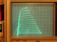
Those curves are stunning: equally spaced and almost vertical! What is the internal resistance of the tube in that configuration? Is there any reliable source for matched 6HB6s?Shunt Schade and CFB have the advantage of tracking non-linearity in the N Fdbk path. (series Schade too, need an interstage xfmr though).
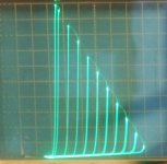
Look at the 6HB6 curves below. 1st pic is g2/g1 triode (like a real triode or UL mode), and the 2nd pic is shunt Schade. Same tube.
Thanks in advance
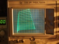
Sorry to quote an old post, I would like to know if you have applied similar feedback with 6550 or other tubes. I would like to build an amp with KT88 or 6550 (I already have the transformers) and I'm indecided between the two.The KT88 with feedback curves are 20% feedback, so effective mu is ~5. The KT88 manages to have better linearity, a lower rp, and higher gain than the 300B, and it can be driven to saturation without g1 power drive.
Thanks in advance.
Roberto
here the curves for triode connection
https://bms.isjtr.ro/sheets/135/6/6550A.pdf, page 5 ( plus the curves for UL)
where the linearity is good
In this configuration the feedback is 100%
with this configuration you can reach the Rp around 800 ohm that in in line with 300B.
The mu is almost the double of 300B.
Walter
https://bms.isjtr.ro/sheets/135/6/6550A.pdf, page 5 ( plus the curves for UL)
where the linearity is good
In this configuration the feedback is 100%
with this configuration you can reach the Rp around 800 ohm that in in line with 300B.
The mu is almost the double of 300B.
Walter
Sorry to quote an old post, I would like to know if you have applied similar feedback with 6550 or other tubes. I would like to build an amp with KT88 or 6550 (I already have the transformers) and I'm indecided between the two.
My experiences with this kind of feedback are summarized here.
I only ran KT88s, but I don't think you would notice any difference between KT88 and 6550 in this configuration. The feedback would swamp the differences in the device characteristics.
Thank you very much SpreadSpectrum, I will try them with 20% local feedback + 23% UL.
I then use some feedback from the anode of KT88s to the grid of the driver, à la RH50W
I then use some feedback from the anode of KT88s to the grid of the driver, à la RH50W
By reading the topic name i thought it's about bootstrapping inputs... looks like clickbite to me...
re: Zintolo
I believe the scaling on that Schaded 6HB6 curve set was 10 mA/div Vert. and 50V/div Horiz. giving approx 200 Ohm Ri.
The 6HB6 tubes are like EL84s with 20,000 gm, quite nice. Unfortunately, according to George at Tubelab, some Hong Kong buyer bought up most of the supply of 6HB6 tubes ( like 30,000 tubes), maybe after seeing that graph. They were on the venerable $1 tube list of TV tubes for a long time. George gave up on some 6HB6 amplifier designs (already PC boarded) after the tube vanished.
I don't think you will find any matched 6HB6s around since they were just TV Vertical amp tubes. One caveat with the 6HB6 was the poor uniformity of biasing.
Another similar tube is the 12HL7, also a video tube with 21000 gm, and a frame grid. It was briefly on the old $1 TV list too, but disappeared quickly.
Another tube is the 9KC6 frame grid dual control tube. You have to put +10 to +13V on grid 3 to square up the pentode knees, but it forms a very nice 32,000 gm, 9 Watt pentode with that fix in place. Should give 125 Ohm Ri Schade curves. I'm not aware of anyone buying those up (odd heater V), yet. It was on the old $1 list, and sometimes available in quantity for $0.50. You won't find any matched ones. And 9KC6 are likely poorly uniform also. Frame grids being very touchy about precision alignment.
Finally, I would mention the 6197 (6CL6) video tube, at 11,000 gm, non frame grid. These are available on Ebay in quantity for less than a $1, and are quite uniform in characteristics in the boxed GE ones.
1) 6HB6 Schade 10 mA/div
2) 9KC6 pentode +12V on grid 3, 10 mA/div
3) 6197 pentode 5 mA/div
Those curves are stunning: equally spaced and almost vertical! What is the internal resistance of the tube in that configuration? Is there any reliable source for matched 6HB6s?
I believe the scaling on that Schaded 6HB6 curve set was 10 mA/div Vert. and 50V/div Horiz. giving approx 200 Ohm Ri.
The 6HB6 tubes are like EL84s with 20,000 gm, quite nice. Unfortunately, according to George at Tubelab, some Hong Kong buyer bought up most of the supply of 6HB6 tubes ( like 30,000 tubes), maybe after seeing that graph. They were on the venerable $1 tube list of TV tubes for a long time. George gave up on some 6HB6 amplifier designs (already PC boarded) after the tube vanished.
I don't think you will find any matched 6HB6s around since they were just TV Vertical amp tubes. One caveat with the 6HB6 was the poor uniformity of biasing.
Another similar tube is the 12HL7, also a video tube with 21000 gm, and a frame grid. It was briefly on the old $1 TV list too, but disappeared quickly.
Another tube is the 9KC6 frame grid dual control tube. You have to put +10 to +13V on grid 3 to square up the pentode knees, but it forms a very nice 32,000 gm, 9 Watt pentode with that fix in place. Should give 125 Ohm Ri Schade curves. I'm not aware of anyone buying those up (odd heater V), yet. It was on the old $1 list, and sometimes available in quantity for $0.50. You won't find any matched ones. And 9KC6 are likely poorly uniform also. Frame grids being very touchy about precision alignment.
Finally, I would mention the 6197 (6CL6) video tube, at 11,000 gm, non frame grid. These are available on Ebay in quantity for less than a $1, and are quite uniform in characteristics in the boxed GE ones.
1) 6HB6 Schade 10 mA/div
2) 9KC6 pentode +12V on grid 3, 10 mA/div
3) 6197 pentode 5 mA/div
Attachments
Last edited:
My experiences with this kind of feedback are summarized here.
Is your amp working with a DF of 3.3 now? Have you kept the local feedback only, without gnfb? I'm playing with DF+UL on another amp and I've one configuration that gives me more attenuation on higher order harmonics even when the amp is saturating (with a DF of 2) whilst the other gives me the same DF you have here but with more high order harmonics.
I don't know which one will sound best with my Klipsch.
My EL84 based amp has a DF of 2 and I'm happy with it.
Yeah, it only uses the local feedback right now with DF of 3.3. I made the amp for my brother so I don't hear it much, but it sounds really nice when I do.
He uses some surprisingly sensitive JBL PA speakers with it (JRX215) and it sounds pretty well in control.
He uses some surprisingly sensitive JBL PA speakers with it (JRX215) and it sounds pretty well in control.
@ smoking-amp :
Thank you for all the shared information, those values are really impressive!
Are they with just 10% Shade?
Thank you for all the shared information, those values are really impressive!
Are they with just 10% Shade?
@ SpreadSpectrum:
https://jblpro.com/en/site_elements/jrx215-spec-sheet
99 dB/Wm! I've never heard them good to know there are some quite cheap speakers that sound good and do not need too much power.
Thanks!
https://jblpro.com/en/site_elements/jrx215-spec-sheet
99 dB/Wm! I've never heard them good to know there are some quite cheap speakers that sound good and do not need too much power.
Thanks!
Hi,
I was investigating about generic feedback and its use and I ran into a particular local feedback loop between grid and cathode of a tube (triode, ecc.). I noticed it's employed especially in certain guitar amps. I wondered if it has any use in tube audio systems too. And how to calculate the the proper cut-off frequency for a generic case. Some informations of the subject are messy.
I once saw a schematic from a Howard Dumble amp, that had this.
It was two (1) meg resistors in series with a 100 pf cap ; on the first input gain stage of an overdrive special....
- Home
- Amplifiers
- Tubes / Valves
- Local feedback between grid-cathode