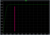
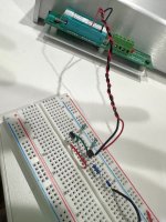
Here's one. It "works with 0,6 V" both in SPICE simulation, and in the real world on the lab bench.Show me a current source which works with 0,6 V ..
_
Attachments

A PNP current mirror with 200 mV of emitter decoupling should do the trick. Or maybe a JFET with low pinch-off voltage.
Yes, I did not consider a mirror, only "classical" current sources.
In some very famous and popular threads about regulators here a JFET is used as current source
with less than a single Vbe drop, there is a source resistor in series. I am not convinced this works.
In some very famous and popular threads about regulators here a JFET is used as current source
with less than a single Vbe drop, there is a source resistor in series. I am not convinced this works.
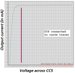
LSK170A, although 0.6 V is on the low side even for an LSK170A. Its output conductance is less than that of a linear resistor conducting the same current at 0.6 V, but not orders of magnitude smaller.
It works! I just simulated and the load regulation is improved by over 10 times.

A comparison with direct drive of the output base would be interesting, like in the original post
I also think the schematic in post#1 is no good.I will not do such a thing, the schematic from the first post is fundamentally wrong, there is no current path to ensure the blocking of the series transistor, which results in a very poor quality dynamic behavior.
There are a number of improvements to make.
Several have been mentioned in this thread.
Best would be a totally new design 🙂
A B-E resistor can do that job cheaply and effectivelyI will not do such a thing, the schematic from the first post is fundamentally wrong, there is no current path to ensure the blocking of the series transistor, which results in a very poor quality dynamic behavior.
It works! I just simulated and the load regulation is improved by over 10 times.
post 1 circuit was 200mV, for your circuit graph shows 80mV 🤔
With some optimisation it was 2-3mV and under 1mV with darlington. The optimisation includes compensation too, but this schematic is made wit different transistors, available in library.
Also the output currents are different.
În fact on that version the difference was 72mV but this is not important, more important is that in the same analize you have the same schematic and values, version with simple resistor and version with current mirror. Is not correct to compare the schematic from first posts made with different transistors and in a different simulator whit this.
Last edited:
Exact but in this case will not be the schematic from original post and will became more the schematic from my simulation.A B-E resistor can do that job cheaply and effectively
- Home
- Amplifiers
- Power Supplies
- load regulation