"A B-E resistor can do that job cheaply and effectively", then
"Exact but in this case will not be the schematic from original post"
What is going on here ? You had the BE resistor in your simulation
of post 32 but did not want to compare this to the "original post"
without any resistor as requested by me in p. 33.
So where is your "original post" ? My original post is number 1 here.
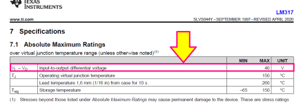
Maybe someone will tell you how to exploit an often-misunderstood specification on the LM317 {adjustable voltage regulator IC} datasheet: "Absolute maximum input-to-output differential voltage" must be 39.99 volts or less.
This does not mean you can't apply 58 volts to the input of an LM317. You can and the datasheet allows it. This does not mean you can't apply 99 volts to the input of an LM317. You can and the datasheet allows it.
The "Absolute Maximum" constraint applies to the differential voltage, (Vin - Vout). Not to the magnitude of Vin or the magnitude of Vout. Only to the difference between them.
The datasheet simply requires that when Vin is 58 volts, Vout MUST be greater than 18 volts. And your circuit obeys this requirement (in its equilibrium state): Your Vin is 58V, your Vout is 48 volts, and your Vin-Vout is only 10 volts. Easily within spec. All you have to do is make sure this is also true during power-up and power-down.
The LM317 is widely available, even in Ecuador, even in Portugal, even in Romania, even in the UK. And it's cheap. And it is offered in a TO-220 thru hole package with a mounting tab, which lets you bolt it to a big heatsink if you want. LM317 has excellent load regulation, excellent line regulation (also called "PSRR"), and very good voltage precision.
All you have to do is figure out ancillary circuitry which absolutely guarantees beyond a shadow of a doubt, that your circuit always always always has Vout > (Vin - 39.9 volts). Even during power-up. Luckily this is both possible and dirt cheap. The whole thing is a single LM317 plus approximately 8 other components. No additional transistors, no additional ICs, no additional optoisolators.
_
Attachments
Last edited:

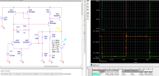
post 1 circuit was 200mV, for your circuit graph shows 80mV 🤔
In this version the voltage difference for a current variation from 15mA to 30mA is only 370µV, so over 500 times better (compared with 200mV).
And the input ripple is reduced by over 250 times.
Attachments
Last edited:
there is no current path to ensure the blocking of the series transistor, which results in a very poor quality dynamic behavior.
under what circumstances does this cause problems ?
Very simple. When you have a rapid negative current variation without discearge path for base current will result finally a huge voltage spike.
At #45 I post a working regulator schematic and I respond to a question from #47. I interpreted the question generic not to a specific schematic.
Why you ask? Now I try to respond to #48
Why you ask? Now I try to respond to #48
https://www.diyaudio.com/community/attachments/reg1-jpg.1263708/
under what circumstances does this cause problems ?
the schematic from the first post is fundamentally wrong, there is no current path to ensure the blocking of the series transistor, which results in a very poor quality dynamic behavior.
When you have a rapid negative current variation without discearge path for base current will result finally a huge voltage spike.
under what circumstances does this cause problems ?
If you don't know why a system must have a fast and accurate response, I don't have the time or inclination to explain something like that.
Ask those who use parallel stabilizers for example, maybe they would like to explain.
Load regulation, line regulation, CMRR, (almost) all measurable parameters will deteriorate drastically as the frequency increases above a few tens of hertz.
The first scheme is only slightly better than a simple zener. Put 2-3 series and you get about the same performance.
Last edited:
I will not do such a thing, the schematic from the first post is fundamentally wrong, there is no current path to ensure the blocking of the series transistor, which results in a very poor quality dynamic behavior.
A B-E resistor can do that job cheaply and effectively
in the original design there is current limiting D1-3 and R7, maybe these also serve that purpose ?
- Home
- Amplifiers
- Power Supplies
- load regulation