Segran, look at figure 7 here for another solution:http://www.national.com/an/AN/AN-1850.pdf
I have played around with the resistor values and found a mix that keeps the quiscient current within 5mA over 35 - 50 degrees C, from 145mA dropping to 140mA. Also found that around 150mA is a fair compromise.
I've spent many, many hours listening to the amp, still one channel MOSFET while the other is BJT. After careful consideration I find the MOSFET sound slightly, but distinctly, more agreeable to my (and my families) ears. Why I don't know but it seems to have something to do with odd/even harmonics. Too bad I don't have the equipment needed to analyze this in depth.
Happy new year everyone & happy watts!!
I am looking into using the schematic of figure 3 in the application note below
http://www.national.com/an/AN/AN-1850.pdf
to make a roughly 200~300W/ch@8ohm amp
I've got 3 questions:
1) Can I exchange the Toshiba 2SK1530/2SJ201 pairs used in the AN with Fairchild IRFP240/IRFP9240 without changing anything else? i.e. the values of resistors RG and RE ? the fairchild units seem a bit cheaper and want to give them a go for this first attempt
2) Can I add a third or even forth pair of mosfets to get more power? Do I need to make any changes to the circuit?
3) I plan to apply +/- 70~80 Volts Vcc & Vee. What power is that going to give?
Thanks
If you want to run 70 - 80V then you need to add more output transistors, 3 pair at a minimum, better to do 4 pair (you need to do some SOA and thermal calculations). The 2 things that will need to change are the bias resistor values (based on what you choose and how you want the current to vary with temperature) and then you should add a extra driver stage in case you need it with 4 pairs of devices. The LM49810/30 are good up to 2 pairs but there is no data from National on using more than 2 pairs. Check out AN-1645 for info on using the devices you want. That note tests several devices with the LM4702 but the biasing will be similar. That note only tested 1 pair of devices but will give you some info.
-TH
-TH
Hello Everyone!
Here is my second generation of LME49810+ThermalTrak amplifier, named Initial Power Amp. The chip is on a separate board so that I can make measurement to it easier. The two PCB's are connected via pin headers. I plan to have multiple Driver+Output boards for testing different BJT's/MOSFET's.
The new layout achieves a lower THD compared to that of the pervious PCB. I will post some data later.
Attachments
panson_hk said:...
Here is my second generation of LME49810+ThermalTrak amplifier, named Initial Power Amp. The chip is on a separate board so that I can make measurement to it easier. The two PCB's are connected via pin headers. I plan to have multiple Driver+Output boards for testing different BJT's/MOSFET's.
...
Nice job panson_hk!

Please take it if you like. You can even use LME49830 if you like. 😉
An externally hosted image should be here but it was not working when we last tested it.
Lazy Cat said:Please take it if you like. You can even use LME49830 if you like. 😉
What is the purpose of this output stage and its advantage?

And here is the ProJet Power Module 
An externally hosted image should be here but it was not working when we last tested it.
This is a really neat looking power amp module!Lazy Cat said:And here is the ProJet Power Module
....

Do you have any specs on it? How about PCB files?
Thanks!
Lazy Cat said:And here is the ProJet Power Module
Very nice module!
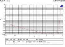
Here is THD measurement comparison between LME49810 alone and with driver+output BJT's (8Ohm load) of my new layout. The overall amplifier clips at about 30Vrms (=112W, 8Ohm). You can see that below 20Vrms the driver and output BJT's contribute very little extra distortion.
Attachments
One more data to share here.
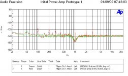
FFT of THD+N residual of LME49810 alone and the overall amplifier driving 8 Ohm for 10 W (8.94Vrms).
The 100 Hz hum is much higher when driving an 8 Ohm load. However, the driver+Output BJT's do not produce additional harmonics contents (>3rd) at this output level.
FFT of THD+N residual of LME49810 alone and the overall amplifier driving 8 Ohm for 10 W (8.94Vrms).
The 100 Hz hum is much higher when driving an 8 Ohm load. However, the driver+Output BJT's do not produce additional harmonics contents (>3rd) at this output level.
Attachments
Hi every body there!
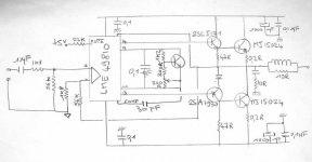
inspired by this thread, I have built a four channel amp using lme49810, a driver stage and a quasi complementary output stage with one pair of mj15024 each, and no current limiter. I use them as mid and treble amps in my three amped hifi system (8 ohms sppeakers). It is working fine with supply rails of +/-45volts.
I was wondering how high can i go with supply rails staying under SOA limits.
Thank you for your help.
I did some numbers on 1pair MJ21193
On +-50Vdc from 35Vac you can get 170W into 4r0 @ 60degree phase angle if you keep the heatsink cold. Quasi bias should allow this.
On +-60Vdc from 40Vac you can get 150W into 8r0 @ 60degree phase angle to the same conditions.
I don't have ONsemi data for 100mS SOA but I'm guessing from other devices that your 15024 will work at these voltages, but not for PA or disco duty.
from 0V to 70Vce both these devices take the full Tc=25degC 250W.
They are effectively identical at these lower voltages as far as SOA and temperature de-rated SOA are concerned.
Vce>80V is not critical to audio amplifiers running on 35Vac or 40Vac transformers into reactive speaker loads.
I wish you had looked at both datasheets to save me the time to consult both.
Andrew,
yes i looked at both but i am not so familiar with these curves . these two are not so easy to compare because one is for 300ms (15024) and the other one for 1 second. Slopes are different too.
Anyway i understand that i have been a bit shie untill now with these devices.
Here is my schematic. comments are welcome.
Attachments
- Home
- Amplifiers
- Chip Amps
- LME49810 - a new cousin for LM4702