In this AN-1850 p 13, is there not a contradiction between the first sentence and the choice of the recommended value?
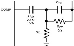
Citation: "...A value (of CC2) five times CC1 is a safe starting point. The resistance value is then selected based on the location of the desired pole. Recommended starting values are 12pF for CC2 and 5.1kΩ for RC1."
Citation: "...A value (of CC2) five times CC1 is a safe starting point. The resistance value is then selected based on the location of the desired pole. Recommended starting values are 12pF for CC2 and 5.1kΩ for RC1."
Attachments
jackinnj said:
They really designed the LME49830 for these devices in mind. The LM4702/LME49811 will drive the lateral MOSFETs with no problems.
You might want to consider the Fairchild FQA12P20 and FQA19N20 devices -- a bit less expensive than the Vishay/IRF.
Yes right...
Is there any relation that calcuates current required per mosfet gate for maximum 20 khz. yes capacity of gate is known in the datasheet of each mosfet, but for precautions whats the best relation
And does LME49810 outputs 60mA max per rail or together ? I mean if amplifier has 6 mosfets or 3 pairs for exaple, than I in gate calculation take ONLY 3 mosfets cause its AB class , they are never opened together
What abou "subjective" audio quality is it better than for example well known Leach amplifier? I presume this LME has lower THD..
Audioman is talking about the LM4702/LME49811. The LME49810 and LME49830 do not NEED these additional caps. Only the compensation capacitor is needed. AN-1850 shows that additional optimization can be accomplished with a more complicated compensation network.
-TH
-TH
I see now that LME as ALSO only +/- 6V differential voltage . thats NOT good for IRFP240, cause bias current will be to low resulting higher THD..
Would it be possible to increase that voltage and how ?
Would it be possible to increase that voltage and how ?
grizlimedo said:I see now that LME as ALSO only +/- 6V differential voltage . thats NOT good for IRFP240, cause bias current will be to low resulting higher THD..
Would it be possible to increase that voltage and how ?
Use the LME49830.
The LM4702 does not have much bias voltage range, ~7V max. The LME49810 has 11V and the LME49830 has 16V. Pick the part that will drive the devices you want to use. Otherwise you will have to add additional circuitry, no way to increase these limits on the parts.
-TH
-TH
SpittinLLama said:The LM4702 does not have much bias voltage range, ~7V max. The LME49810 has 11V and the LME49830 has 16V. Pick the part that will drive the devices you want to use. Otherwise you will have to add additional circuitry, no way to increase these limits on the parts.
-TH
but aditinaly circuit for sure can increase bias voltage for mosfet !! why not use LME49810 which is CHEAPER and aditonal bipolars that can drive mosfets ?
grizlimedo said:
but aditinaly circuit for sure can increase bias voltage for mosfet !! why not use LME49810 which is CHEAPER and aditonal bipolars that can drive mosfets ?
if you use emitter follower and source follower you need even more voltage to bias the output stage.
You could try using a CFP output stage, but I don't like your chances of getting a stable amplifier. i.e. emitter follower and common source biased by the collector load of the follower.
prototype board
What would be the easiest adaptation proto board breadboard or perf board to play with the lme49810 knowing that the pitch of the pins is 1mm
JPV
What would be the easiest adaptation proto board breadboard or perf board to play with the lme49810 knowing that the pitch of the pins is 1mm
JPV
Re: prototype board
I have on the drawing board here a PCB for use with these LME chips -- and the LM4780 as well.
GB Anyone?
JPV said:What would be the easiest adaptation proto board breadboard or perf board to play with the lme49810 knowing that the pitch of the pins is 1mm
JPV
I have on the drawing board here a PCB for use with these LME chips -- and the LM4780 as well.
GB Anyone?
OK, this is a first shot -- I am open to suggestion -- note that pins 7 and 9 of the LME49810,11,30 are NC -- so I use them -- I am thinking of having 8 LME's on a PCB, as well as 8 SOIC8 and 4 SOIC14 so I can stop purchasing adapters:
An externally hosted image should be here but it was not working when we last tested it.
Like this -- probably about $4 or $5/board -- depending upon shipping.
An externally hosted image should be here but it was not working when we last tested it.
AndrewT said:
if you use emitter follower and source follower you need even more voltage to bias the output stage.
You could try using a CFP output stage, but I don't like your chances of getting a stable amplifier. i.e. emitter follower and common source biased by the collector load of the follower.
CFP.. can you explain more about that
bobodioulasso said:Lazy cat,
Thank you for your design. Is this original idea from you? Never seen before such a topology. Very clever. I'll try it one day.
In this kind of configuration with MOS-FET driver, yes. I even called it BIGBT for which I see that you found my thread.
Try it you won't be disappointed. In this configuration LME has more breathe and works very easy with low Z speakers. It is really very powerful, including high dumping factor and best of all you can go to +/- 100v supply rails to full power. 😉


- Home
- Amplifiers
- Chip Amps
- LME49810 - a new cousin for LM4702