Yes, still working on that...Is that in the MOSFET amp?
You can put diodes that you keep away from the heatsink in series with the C-B resistor of the bias transistor
OK, I increased R13 from 1k2 to 5k6 and R34 from 220R to 470R at first, but now R34 is 820R since I still felt I had to much heat dissipation from the drivers. Driver bias current is now 9mA while output bias is 45mA.
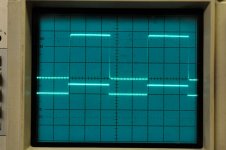
Here is a shot of the square wave response (upper) using the calibration output (lower) on the scope as signal source (1kHz 300mV). I think it looks pretty good, any comments?
Attachments
Segran said:
Yes, still working on that...
OK, I increased R13 from 1k2 to 5k6 and R34 from 220R to 470R at first, but now R34 is 820R since I still felt I had to much heat dissipation from the drivers. Driver bias current is now 9mA while output bias is 45mA.
Here is a shot of the square wave response (upper) using the calibration output (lower) on the scope as signal source (1kHz 300mV). I think it looks pretty good, any comments?
How about 50Hz and 20kHz Wave?
My measure my Amplifier in 50Hz square wave.
It's a little not good, having a little slope.
I think it might be produced by input capacity.
How about 50Hz and 20kHz Wave?
As I use the calibration output of my scope for square wave generation I can't change the frequency. I use an old laptop PC to generate sine waves but the square waves from that are so full of ringing that it's virtually useless.
I have tried both 1 and 2 diodes in serie with R13 but there is no noticeable effect on temperature stability. In fact, it became slightly worse.
Instead I have decided to increase the quiscient current to 125mA, heating up the heatsink to 35 degrees , temperature is much more stabile if I run it a bit hotter. And I guess it's better that bias decreases slightly with temperature than increases...
I also changed from IRFP 240/9240 to IRFP 340/9240 as the latter is a better match on RDSon for one thing. That removed the last (hardly noticeable) hump) on the rising and falling flanks of the square wave.
I tried the G-S zener protection diodes (10v + 1N4148)again, although VGS (p-p) is lower that the zener voltage the diodes causes massive distortion. The zeners are gone for good now, I think.
With this I am satisfied with the performance of the amp, so tomorrow I will make 2 new and revised PCB's and assemble the other channel.
Some circuits use a mosfet for Q1, that could be a solution to overcompensated bias if the diodes don't work. R13, R14 and P1 will need other values if that is done.
I will try that after X-mas. I guess I have to use wires between the PCB and the Mosfet, can't find any with the same pin configuration as BD139.😡Some circuits use a mosfet for Q1
Any suggestion where to start on R13/14/P1?

I have assembled and tested the 2nd generation of PCB's today, one MOSFET channel and one BJT (2SC500/SA1943). I have compared the two and can't see any difference in distortion or bandwidth. The square wave reponse 99.9% equal. I can't hear any (objective) difference either, which is what I wanted to find out for myself. Lot's of talk about this, that and the other being "better"...😱
The BJT produces +150W, while the MOSFET gives 125W, running on +/-49V supply, supply voltage drop by +/-6V under full load conditions. I guess I could do with a bigger transformer - if I was chasing numbers....🙂
LME49830 is running hotter than LME49810, haven't measured exactly how much yet. But a 8degree/W heatsink is recommended on the 49830 while 49810 could do with less.
Merry X-mas to all of you that have helped me getting this far!

is that into 4r0? I would expect around 100W into 8r0 and 180 to 190W into 4r0 from the BJT version.Segran said:.........The BJT produces +150W, while the MOSFET gives 125W, running on +/-49V supply, supply voltage drop by +/-6V under full load conditions. I guess I could do with a bigger transformer - if I was chasing numbers....🙂
It's not about chasing numbers. It's about stiff supplies that don't collapse when asked to deliver transient currents.
Segran, look at figure 7 here for another solution:
http://www.national.com/an/AN/AN-1850.pdf
Wasn't that the one you had in your BJT amp at first? That explains why you had problems, it was for MOSFETs. Rb3 is the resistor that decreases the temperature coefficient.
http://www.national.com/an/AN/AN-1850.pdf
Wasn't that the one you had in your BJT amp at first? That explains why you had problems, it was for MOSFETs. Rb3 is the resistor that decreases the temperature coefficient.
Is there an idiot-proof LME49810 implementation?
Also, I'm working on a 3-way with three eight-ohm woofers in parallel. What would be the easiest way to power these? I presume I could gang up multiple parallel output transistors?
Also, I'm working on a 3-way with three eight-ohm woofers in parallel. What would be the easiest way to power these? I presume I could gang up multiple parallel output transistors?
Actually, it's 5R3 - I burned one of my (undersized) power resistors... And i wrote "+150W" as the soldering between the remaining resistors melted so I couldn't complete the measuring. It had more to give.is that into 4r0?
I will redo the measuring as soon as I get resistors with an adequate power rating.
I can't stand being in the same room while blasting out full power sine wave from my speakers. The speaker elements are rated 100W so I wouldn't only risk my reamaining hearing ability (and sanity) but also (yet another set) of speaker elements.
It's not about chasing numbers. It's about stiff supplies
I agree, the "sagging" came from my small Variac which also was set higher to give +-55VDC on the PS (I always use that when firing up stuff for the first time). The tranny is 2x35VAC 300VA, giving +/-49V. Running direct from mains supply there is very little sagging, and the the output power is TBD (waiting for resistors!).
What I meant by bigger was actually more voltage than VA. But since all my speakers are rated 100W except my Kef Q5 which are rated 160W there is really no point in trying to crank more power out the amp. But I have left space around the transformer for a 500VA 2x55V....
Segran, look at figure 7 here for another solution:
I KNEW that I got it from somewhere, and rememberd reading about it. But I couldn't remember where.... Thanks Jocke, this will will try, it's an easy mod. Too bad that I have made new PCB's already....
Maybe I missed it or was lazy to read all the post, but why are you using a driver stage with the LME49810 or LME49830 driving MOSFETs? Are you using more than 2 output devices per side or just similar to the AN-1850 design? If you are using a design similar to the AN-1850 then a driver stage is not going to help much. When I was testing the LME49830 with or without a driver stage, I could not find any benefit (in measurements) to having a driver stage. The downside is loss in output power because you lose 0.5V+ of gate drive voltage.
-TH
-TH
Drivers or no drivers
I started out using LME49810 and TIP35/36 without drivers, and that still works fine. However, not using drivers was heavily criticized by a number of higly respected guys here at diyAudio. The main shortcomings where said to be that 49810 only can drive one pair of BJT's and that slew rate is better when using drivers. Panson Poon have made some serious testing of 49810 w/wo drivers, his reports are published in this thread.
Anyhow, I was recommended to incorporate drivers in my next design, wich was intended as a generic PCB for both 49810/BJT's and 49830/MOSFET's. That's where I am right now, trying to fine tune the temperature stablity of the MOSFET's. The BJT worked to my full satisfaction from the start-up.
One reason for using drivers is that I may add more BJT output pairs later on, the PCB has provisions for that as well.
I am aware that drivers for the MOSFET is probably an overkill even if I used two MOSFET pairs. But then again, who knows if I later on decide to use the same PCB with 3 or more pairs!
why are you using a driver stage with the LME49810 or LME49830 driving MOSFETs?
I started out using LME49810 and TIP35/36 without drivers, and that still works fine. However, not using drivers was heavily criticized by a number of higly respected guys here at diyAudio. The main shortcomings where said to be that 49810 only can drive one pair of BJT's and that slew rate is better when using drivers. Panson Poon have made some serious testing of 49810 w/wo drivers, his reports are published in this thread.
Anyhow, I was recommended to incorporate drivers in my next design, wich was intended as a generic PCB for both 49810/BJT's and 49830/MOSFET's. That's where I am right now, trying to fine tune the temperature stablity of the MOSFET's. The BJT worked to my full satisfaction from the start-up.
One reason for using drivers is that I may add more BJT output pairs later on, the PCB has provisions for that as well.
I am aware that drivers for the MOSFET is probably an overkill even if I used two MOSFET pairs. But then again, who knows if I later on decide to use the same PCB with 3 or more pairs!
Yes, if using BJTs in the output stage then a driver stage is best. If only using MOSFETs then, at least to 2 devices per side (4 total in the output stage) then a driver stage is not needed. What I did on one design that was similar to your in that is was for both LME49810 and LME49830 was to just jumper the driver stage when using FETs or fill in the driver stage when using BJTs.
Sounds like you have a good design going there.
-TH
Sounds like you have a good design going there.
-TH
I was once a treehouse, I lived in a cake
OT: I belive this is the original song:
http://www.youtube.com/watch?v=HbPDKHXWlLQ
Even more llamas! 😀
OT: I belive this is the original song:
http://www.youtube.com/watch?v=HbPDKHXWlLQ
Even more llamas! 😀

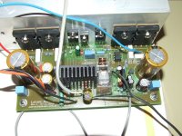
My second two channels Power Amplifier using LME4910 driver and MOTOROLA MJ15003/MJ15004 Power Transistors.
It is similar to my first one(On Post #579).
I add MKP-capacities on capacities for power transistors in second Power Amplifier.
The following are wave-test measured by oscilloscope.
I use 8R resistor as load
(The wave in the upper half of screen is load, and the another half of screen is function generator)
<Sine wave>
100Hz
1kHz
20kHz
<Square wave>
60Hz
100Hz
1kHz
20kHz
40kHz
Why the square wave of 20kHz and 40kHz on load is better than function generator?
I think the cable between Power Amplifier Singnal Input and oscilloscope is older.
It is similar to my first one(On Post #579).
I add MKP-capacities on capacities for power transistors in second Power Amplifier.
An externally hosted image should be here but it was not working when we last tested it.
The following are wave-test measured by oscilloscope.
I use 8R resistor as load
(The wave in the upper half of screen is load, and the another half of screen is function generator)
<Sine wave>
100Hz
An externally hosted image should be here but it was not working when we last tested it.
1kHz
An externally hosted image should be here but it was not working when we last tested it.
20kHz
An externally hosted image should be here but it was not working when we last tested it.
<Square wave>
60Hz
An externally hosted image should be here but it was not working when we last tested it.
100Hz
An externally hosted image should be here but it was not working when we last tested it.
1kHz
An externally hosted image should be here but it was not working when we last tested it.
20kHz
An externally hosted image should be here but it was not working when we last tested it.
40kHz
An externally hosted image should be here but it was not working when we last tested it.
Why the square wave of 20kHz and 40kHz on load is better than function generator?
I think the cable between Power Amplifier Singnal Input and oscilloscope is older.
hi all
some really awesome implementations here
but thread is becoming quite lengthy
can someone point me to a trusty schematic for a 49810-based amp & its psu ?
I am looking for around 300W @ 8ohm / ch
also anyone selling kits? pls contact by email
thanks
some really awesome implementations here
but thread is becoming quite lengthy
can someone point me to a trusty schematic for a 49810-based amp & its psu ?
I am looking for around 300W @ 8ohm / ch
also anyone selling kits? pls contact by email
thanks
download the datasheet.chatziva said:
can someone point me to a trusty schematic for a 49810-based amp & its psu ?
I am looking for around 300W @ 8ohm / ch
- Home
- Amplifiers
- Chip Amps
- LME49810 - a new cousin for LM4702